


9
5. Radio Control
Connect the “Y” leads to the corresponding connections on the wing.
“Y” Lead No.1 = Connects to the two aileron servos.
“Y” Lead No.5 = Connects to the two main retract units, the remaining plug will be
connected to third retract unit in the tail once the wing and fuselage are joined.
“Y” Lead No.6 = Connects to the two flap servos.
“Y” Lead No.7 = Connects to the bomb doors.
Offer the wing to the fuselage, leading edge first, ensuring that all wiring is kept clear of the
wing seat. Secure the wing in place with the four M4 x 55mm screws.
We recommend that your receiver is mounted in the area behind the ESCs, using self-
adhesive “Velcro” tape.
You must adhere to the receiver manufacturer instructions regarding positioning and
aerial routing.
Connect the ESC power connectors to the motor power leads. You will note they are
numbered 1-4, make certain they are connected accordingly, 1-1, 2-2 etc.
The two servo type leads with only black and red wired from the ESCs supply power to the
wing lights. Connect them to the corresponding wires from the wings.
The lead marked “6” which is fed from one of the power supply cables with a red “T”
connector, is the UBEC. Plug this into any spare channel on your receiver.
The remaining servo control plugs should be connected to the appropriate control outputs
on your receiver.
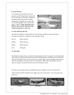
6. Propellers
Please note that the propellers for this model are handed. When viewed from the front, the
left wing motors turn clockwise. The thread on the shafts of these motors is reversed,
i.e.
anticlockwise to tighten.
The motors on the other wing rotate anti-clockwise when viewed from the front and have
handed propellers accordingly. The thread on these motors is conventional,
i.e. clockwise
to tighten.
Propeller Rotation (
viewed from front)
© Copyright Century UK Limited 2012 www.centuryuk.com


