background image

 Manual CT35-IP & CT45IP                                                                          Last update:December 2013


www.max-power.com 

14 

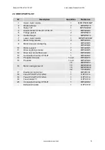
22. SPARE PARTS LIST 


N° 

Description 

Quantités 

Référence 

Upper motor casing 

MPOP5835/SUP 

Backing flange 

MPOP5215 

Relay 12V 

MP053028/2 

Electric Motor CT35-IP / CT45-IP 

MP023000 

Flange gasket 

MPOP5831 

Centre flange 

MPOP5214 

Lower motor casing 

MPOP5835/INF 

Motor fixing screws 

MP024030 

Motor drive pin and spring 

MP025095 

MP025096 

10 

Motor support 

MP028005 

11 

Drive leg fixing screws 

MP024025 

12 

Drive leg / tunnel fibre seal 

MP025090 

13 

Composite drive leg CT35-IP 

MP028000 

14 

Propeller drive pin 

1 ou 2 

MP025070 

15 

Propeller 

1 ou 2 

MP025000 

16 

Motor casing screw kit 

15 

15 

15 

30 

MPOP4051 

MPOP4049 

MPOP4048 

VP084200 

17 

Electronic control box 

MP0P5701 

18 

Fuse CT35-IP 12V (125A) 

OPTI3114 

18 

Fuse CT45-IP 12V (125A) 

OPTI3114 

19 

Fuse holder T1 

OPTI3119 

20 

Composite drive leg CT45-IP 

MP028002 

Extraction handle 

OPTI3118 


Summary of Contents for CT35-IP

Page 1: ...ted Thruster With electronic thruster control CERTIFIED ISO 8846 INSTALLATION OPERATION MAINTENANCE Serial No Installation date THIS MANUAL MUST BE KEPT ONBOARD AT ALL TIMES Via Philips 5 20900 Monza MI Italy Tel 39 039 200 1973 936 Fax 39 039 2004299 www max power com E mail contact max power com ...

Page 2: ...arranty coverage 16 26 Warranty form 18 The use of qualified marine personnel with experience in bow thruster installation is strongly advised Where possible the boat manufacturer s design departments architects and or shipyards should be consulted prior to installation taking place For any boat requiring official classification bodies of approval should also be consulted at the earliest opportuni...

Page 3: ...essive loss of performance Whether inclined or horizontal it is recommended to support the electric motor The batteries used by the thruster must be charged by both the main engine s alternator and an appropriate battery charger If the thruster is installed using a dedicated battery bank this must be as close as possible to the thruster in order to reduce voltage loss in the electric cables For th...

Page 4: ...It is advisable to drill the tunnel before laminating it into position See section 3 Composite Motor Support and Drive leg for more details Replace the tunnel To secure its position apply reinforced fibreglass filler to all areas both inside and out taking care to entirely fill the space between the hull and the tunnel Laminate using a minimum of 8 layers of ISOPHTALIC RESIN alternated with mat an...

Page 5: ...e motor support and the leg s gasket to mark these holes In some cases it will be easier to mark and drill these holes BEFORE laminating the tunnel After drilling use the gasket to verify the holes axes and adjust them with a round file where necessary These holes must be completely clean before inserting the screws Position the leg the gasket between the leg and the tunnel and the motor support a...

Page 6: ...smooth exterior radius and repeat the previous steps Position the four 6 mm motor support screws then tighten them alternatively maximum torque 20 Nm 5 PROPELLER S Insert the drive pin and propeller to be carried out twice for the CT45 IP duo Check that the propeller s turn s without resistance a little resistance due to the motor is normal Gradually tighten the 13 mm nut while holding the propell...

Page 7: ...ve cables Recommended cable sections Cable lengths CT35 IP CT45 IP 12 V L 5 m 2 5 x 2 50 mm 5 L 10 m 5 x 2 70 mm 10 L 15 m 7 5 x 2 95 mm 15 L 20 m 10 x 2 120 mm For all connections use appropriate terminals for the cable sections chosen It is possible to reduce the cable section to facilitate easy connection but only over a short distance In this case appropriated crimp fittings should be used at ...

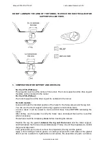
Page 8: ...connections p 12 for more detail on the wiring of the control box to the thruster 11 CONTROL PANEL AND THRUSTER CONTROL BOX FUNCTIONS To switch the thruster ON or OFF follow the instructions given in the diagrams on the following page When switched ON the control panel will beep once and the green LED in the red push button will light up When switched OFF the control panel will beep twice and the ...

Page 9: ...ositioning of the unit clip on the face panel cover Please note that panels are only fully waterproof from the front if installed correctly However the area behind the dashboard should be kept dry to avoid the risk of oxidization of the cable connecter contacts For full control panel installation instructions please refer to the Installation Guidelines as supplied with each control panel 13 TESTS ...

Page 10: ...h and manual battery isolator switched on Switch on the control panel as previously described in the manual Push the red button or incline the joystick to the left and the boat moves to the left Push the green button or incline joystick to the right and the boat moves to the right If during tests the boat moves in the wrong direction change around the blue and the brown wires on your power relay W...

Page 11: ...ly as voltage drop is the most frequent cause of rapid deterioration of the relay Carry out a regular check of all electric components batteries connections power cables NOTE All maintenance should be carried out by qualified and authorised personnel Composite drive leg and propellers The composite drive leg is pre filled with oil and sealed for life It does not require the oil changing The compos...

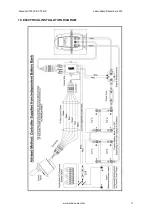
Page 12: ...Manual CT35 IP CT45IP Last update December 2013 www max power com 11 19 ELECTRICAL INSTALLATION DIAGRAM ...

Page 13: ...Manual CT35 IP CT45IP Last update December 2013 www max power com 12 20 RELAY AND CONTROL BOX CONNECTIONS ...

Page 14: ...Manual CT35 IP CT45IP Last update December 2013 www max power com 13 21 SPARE PARTS DIAGRAM ...

Page 15: ...rews 4 MP024030 9 Motor drive pin and spring 1 MP025095 MP025096 10 Motor support 1 MP028005 11 Drive leg fixing screws 2 MP024025 12 Drive leg tunnel fibre seal 1 MP025090 13 Composite drive leg CT35 IP 1 MP028000 14 Propeller drive pin 1 ou 2 MP025070 15 Propeller 1 ou 2 MP025000 16 Motor casing screw kit 15 15 15 30 MPOP4051 MPOP4049 MPOP4048 VP084200 17 Electronic control box 1 MP0P5701 18 Fus...

Page 16: ...tions and connections Check the internal relay contacts WARNING Only a qualified technician should check these points to ensure that the thruster is correctly reassembled and remains Ignition Protected The motor is running but the thruster is not working Check the propellers are fitted Check the motor drive leg assembly Check that the tunnel is not obstructed or the propellors blocked The thruster...

Page 17: ...ser This excludes any damage or faults occurring from normal wear and tear on the following items engine oil seals relay contacts If warranty is registered within the 3 month period following installation 5 Warranty Exclusions Damage due to modifications or installation contrary to published specifications Cost of hauling the boat Damage due to repairs performed by an unauthorized service centre D...

Reviews: