


MAULE AEROSPACE TECHNOLOGY, INC.
MAINTENANCE MANUAL
FOR
M-4-180V
29
Rev. A
4/13/16
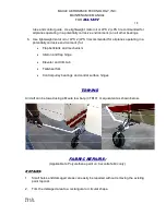
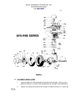
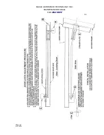
be no looseness or play between the bracket (71B) and the spring.
3.
Install the connector springs, using the heavier spring on the right side. Install
the springs so that the light spring is compressed approximately 112 to 3/4 inch.
4.
Inflate the tire to approximately 20 psi Higher pressure may be used if the wheel
has no tendency to shimmy.
POWER PLANT SYSTEM
The power plant system consists of the engine, engine mount, propeller, cowl, engine
controls, exhaust, air intake system and fuel system.
ENGINE:
Engine instructions covering the care and operation are covered in the engine
manufacturer’s Operator’s Manual.
ENGINE MOUNT:
The engine mount is a welded structure of chrome molybdenum steel (4130) tubing. The
engine is attached to the mount by means of four point suspension to four (4) mounting pads on
the engine case. Each leg attachment incorporates a shock mount designed to absorb torsional
fluctuation and vibrations of the engine. The engine mount assembly is bolted at the firewall to
the fuselage structure by means of four (4) 3/8” attaching bolts, (requiring a torque of 13.3-15.8
ft. lb.) which should be checked for tightness periodically.
An extremely close visual inspection of the engine mount should be made to periodically
check for cracks, dents, weld failures, etc., of the mount tubular members as well as the general
condition of the mount. At regular intervals, the attaching bolts at the engine should be checked
for tightness (required torque value of 40.0-57.5 ft. lb.) The rubber engine mounts should be
carefully inspected and replaced if necessary at each 100-hour inspection. Excessive engine
vibration at various RPM ranges should also prompt their inspection. Care should be exercised
to prevent the rubber mount’s contact with oil as this may result in their premature deterioration.
When torquing any engine or mount bolts, precaution should be taken against any over-
tightening, as this also may cause early failure.
PROPELLER:
The propeller manufacturer’s Installation, Operation and Service manual contains
information on the proper use and care of the propeller.
COWLING AND BAFFLING:
The cowling consists of an upper and lower section. Removal is accomplished by
unlocking the dzus fasteners and removing the AN526 screws.