background image

2

1.1 ASSeMBly iNSTRUCTiONS

MyRide ASSeMBly GUide

Assembly Instructions:

1.  Remove all parts from the packaging and check to make sure that no parts are missing. 

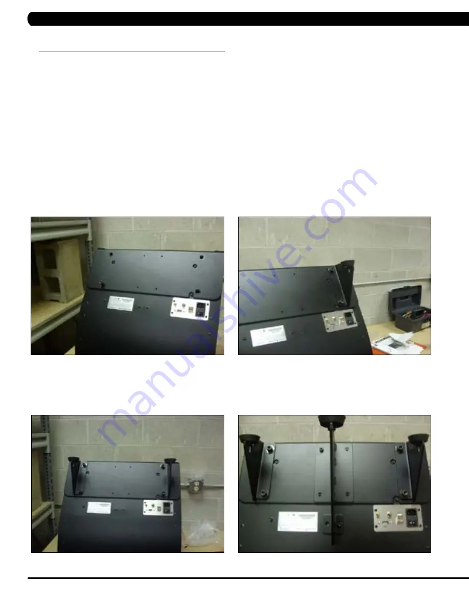
2.  Install the heavy plate on the end of the MyRide frame and secure with a bolt / washer through any of the large mounting holes (Figure A).  

3.  Install one of the fins on the opposite side of the bolt / washer holding the heavy plate to the MyRide frame.  Use 2 large bolts to secure the 

fin to the MyRide frame.  

NOTE: 

 The bend on the fin should be facing the center of the frame (Figure B).  

4.  Remove the bolt / washer holding the heavy plate in place that was installed in Step 2.  

5.  Install the remaining small fin to the MyRide frame.  Use 2 large bolts to secure the fin to the MyRide frame.  

NOTE:

  Again make sure that 

the bend is facing the center of the machine (Figure C).  

6.  Install the large fin with one bolt at the top of the fin and one at the bottom to hold the large fin to the MyRide frame (Figure D).  Push up on 

the large fin so that the holes in the fin align with the bottom of the slots, then install the remaining mounting bolts.  

FiGURe A

FiGURe d

FiGURe C

FiGURe B

ASSeMBliNG THe MyRide

Parts List:


Heavy Plate

Stabilizer Fin - Right

Stabilizer Fin - Left

Stabilizer Fin - Large Middle

Power Cord

Hardware Bag - Contains hardware, pads, and levelers

5mm Allen Wrench

8mm Allen Wrench

Summary of Contents for MyRide

Page 1: ...M y R i d e S E R V I C E M A N U A l ...

Page 2: ...r holding the heavy plate in place that was installed in Step 2 5 Install the remaining small fin to the MyRide frame Use 2 large bolts to secure the fin to the MyRide frame NOTE Again make sure that the bend is facing the center of the machine Figure C 6 Install the large fin with one bolt at the top of the fin and one at the bottom to hold the large fin to the MyRide frame Figure D Push up on th...

Page 3: ...are the at top of the plate 8 Apply foam pieces to each corner of the plate Figure E 9 Carefully lower the unit on its side and raise the heavy end so that it is in position to be viewed 10 Plug in the power cord and turn the machine on using the power switch Make sure that the screen is in position to be viewed MyRide Assembly Guide 1 1 ASSEMBLY INSTRUCTIONS CONTINUED ...

Page 4: ... removed 4 After the monitor reboots it will ask you If Calibration is Required Please Touch Screen Now Figure B Touch the screen letters above to change to the calibration screen this screen will be white with flashing circles NOTE You must touch the screen for calibration within 10 seconds If you fail to do so you will have to power down and reboot the unit as you will not have touch screen func...

Page 5: ... box to remove it Press and release on the TV to add the check mark if not there to activate the TV tuner 8 Press the system line and compare the HDD serial number that is on the label see Figure A with the one displayed on the screen they should be the same Figure D 9 Press Home to return to the home page Test the various sections for proper operation 10 If the product is not being registered imm...

Page 6: ... 2 Once the club has established an account the MyRide unit can be registered a Enter the user name and password created in Step 1 to access your account This should automatically bring you to the registration window b Click on the MyRide v3 Consoles tab c A window will open and give you the option to Register Your Devices d Enter the number you recorded above NOTE This number is also located on t...

Page 7: ...e If the lower LED never turns on red or green check the power jack coming to the monitor and the mini PC using a multi meter Figure B Set the multi meter to DC voltage You should be getting 12V 5 from the power supply to both the monitor and mini PC The inside is positive the outside of the sheathing negative NOTE It is important to check the voltage at both locations as it is possible that one e...

Page 8: ... Check that all 4 cable screws are attached properly Figure B b Disconnect the VGA cable and check that all pins are straight and none of them are missing c Replace the cable if any damage or bent pins are found d Only send a monitor or mini PC after replacing the VGA cable and confirming that it is not the issue NOTE You can use any generic VGA cable like from a computer at the club to test if th...

Page 9: ...itor and mini PC as you interact with the touch screen If this cable is loose or disconnected the screen will not respond to screen touches and will appear frozen Regardless of how the connection looks it is recommended that the USB cable be disconnected then reconnected on both ends The power should then be reset and the display re tested b After power reset attempt to calibrate the touch screen ...

Page 10: ... the ones having the issue a There are some brands of headphones that are known to have communication issues with some type of headphone jacks This issue may be related 2 Check the connection of the headphone jack wire to the mini PC a If the headphone jack wire is tie strapped too tightly to the mini PC it can cause a connection issue b The headphone jack wire should be replaced even if no visibl...

Page 11: ...MATrix Fitness systems corp 1610 Landmark Drive Cottage Grove wi 53527 USA TOLL FREE 866 693 4863 www matrixfitness com FAX 608 839 1717 ko REV 01 ...

Reviews: