background image

36

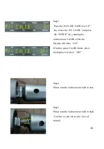
Step6.

Put the incline motor tube on fixed 

stand.

Step5.

Fix the incline motor.

Summary of Contents for MX-A5 Series

Page 1: ...1 MX A5x SERVICE MANUAL...

Page 2: ...SECTION 4 LCB3 LED INSTRUCTIONS 15 1 A5x EP72 LCB3 LED place and definition 16 SECTION 5 TROUBLESHLOOTING 17 1 No display on the console or the display is dim 19 2 All or some of the function keys do...

Page 3: ...3 SECTION 1 MAINTENANCE PROCEDURE...

Page 4: ...build up caused by sweat Use a cotton cloth with water and a mild cleaning product to clean the Suspension Elliptical Trainer Other fabrics including paper towels may scratch the surface Do not use am...

Page 5: ...ration Frequency Every 3 to 4 months CLEANING THE GROOVES Procedure 1 Remove the Poly V belts and check the grooves of the belt for dirt or dust and clean it if any 2 Check the grooves in the pulley f...

Page 6: ...6 SECTION 2 WIRING DIAGRAM INSTRUCTION...

Page 7: ...7 MX A5x WIRING DIAGRAM INSTRUCTION...

Page 8: ...8 P05 Digital cable console cable P04 Pulse sensor wire...

Page 9: ...9 P02 Elevator Wire P14 ECB Load Wire...

Page 10: ...10 SECTION 3 CONSOLE ENGINEERING MODE GUIDE...

Page 11: ...ore up the parameter START Clean accumulate time and distance Hold MANUAL RANDOM for 3 S Enter address SELECT Select address or decrease parameter DOWN Select address or add parameter UP function key...

Page 12: ...12...

Page 13: ...13 MANAGER SCREN DESCRIPTIONS...

Page 14: ...14...

Page 15: ...15 SECTION 4 LCB3 LED INSTRUCTIONS...

Page 16: ...es if the upper console is commanding Elevation 2 DOWN UP1 Indicates if the upper console is commanding Elevation 1 UP UP2 Indicates if the upper console is commanding Elevation 2 UP RPM rotation rate...

Page 17: ...17 SECTION 5 TROUBLESHOOTINGS...

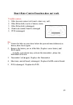
Page 18: ...isplay is dim 2 All or some of the function keys do not respond 3 No resistance change or too hard for pedaling 4 Feel slipping while pedaling 5 Knocking or creaking noises 6 Heart Rate Control functi...

Page 19: ...oard with a new one If it is not replace the generator with a new one No display on the console or the display is dim Possible causes 1 Console is damaged or the console cable is not connected properl...

Page 20: ...not fit in properly 2 Keypad is damaged 3 Upper board is damaged Fix 1 Remove the console cover and then check if keypad cable is connected properly to the upper board If it has not been connected wel...

Page 21: ...D whether is light If not light please replace the LCB 3 Please make use of tools to confirm Generator have conduct 10 15 No resistance change or too hard for pedaling Possible causes 1 Console is dam...

Page 22: ...lt tension is correctly 3 One way bearing is damaged Replace it with a new one instruction see below Knocking or creaking noises Possible causes 1 Pedal is on crank arm too loose 2 Crank or axle is we...

Page 23: ...5 PCB is damaged Fix 1 Center the bike on your chest below the pectoral muscle breast as shown then check again 2 Remove the battery cover of the bike Replace a new battery and check again Actually a...

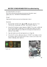
Page 24: ...24 Error Messages on the Console CALIBRATION ERROR REVERSE MOTOR CONNECTION MOTOR UNPLUG MOTOR SYNCHRONIZATION ERROR MOTOR OVER CURRENT COMMUNICATION ERROR MOTOR OVERLOADING Error Definition...

Page 25: ...or damaged Solution 1 Open the incline motor left and right side cove Figure A 2 Press Hold LEVEL both and at the same time for 3 5 sec Then the dot vision display will show MANAGER 3 Select the P11 i...

Page 26: ...lay will show MANAGER Figure A 2 Select the P10 software version and press SELECT key enter confirm the LCB version whether is S004 after if it is S003 before software version please update LCB softwa...

Page 27: ...er is Swing if is Ramp please change to Swing Ramp is for MX I5x I5x only one incline motor A5x have two motor so console missing the one motor signal so console will show the MOTOR UNPLUG 3 Open the...

Page 28: ...ymptom Machine can t start When the replace the new incline motor turn on the power when the display show the REVERSE MOTOR CONNECTION Cause Incline motor inside wire reverse it is spare parts damage...

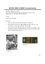
Page 29: ...tor damaged Solution 1 Open the incline motor left and right side cove Figure A 2 Press Hold LEVEL both and at the same time for 3 5 sec Then the dot vision display will show MANAGER 3 Select the P11...

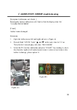
Page 30: ...maged Solution 1 Open the incline motor left and right side cove Figure A 2 Press Hold LEVEL both and at the same time for 3 5 sec Then the dot vision display will show MANAGER 3 Select the P11 inclin...

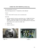
Page 31: ...LCB connect can not communication Solution 1 Open the right disk when the console display show COMMUNICATION ERROR when the LCB LED STATUS will glitter check the console cable with LCB connect whethe...

Page 32: ...32 SECTION 6 Part Replacement Guide...

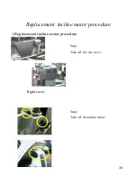
Page 33: ...33 Replacement incline motor procedure 1 Replacement incline motor procedure Step1 Take off the site cover Right cover Step2 Take off the incline motor...

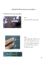
Page 34: ...tor procedure 1 Install incline motor procedure Step1 Connect the incline motor cable Step2 Press Hold both DOWN and UP at the same time for 3 5 sec Then the dot Matrix display will show MANAGER press...

Page 35: ...key running the incline motor CALIB when the Display will show ON If incline motor CALIB finish when the display will show OFF Step4 Please turn the incline motor tube to end Step5 Please turn the in...

Page 36: ...36 Step6 Put the incline motor tube on fixed stand Step5 Fix the incline motor...

Page 37: ...37 Step7 Assemble the site cover Remarks 1 Please assemble 1st incline motor then do the auto calibration then assemble the other incline motor and do the auto calibration again...

Page 38: ...38 SECTION 7 SOFTWARE UPGRADE PROCEDURE...

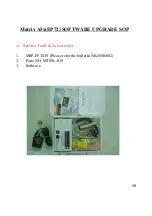
Page 39: ...39 Matrix A5x EP72 SOFTWARE UPGRADE SOP A Service Tools Accessories 1 MSP FET430 Please refer the bulletin NB 0506002 2 Parts NO MT00L 039 3 Software...

Page 40: ...meter Press the File Name Find out the software version file in the computer and then actuate open the file 1 2 4 3 5 6 Note When upgrade LCB the device type 3 has to select MSP430 F135 When upgrade P...

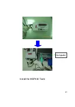
Page 41: ...41 Install the MSP430 Tools Computer...

Page 42: ...42 Press the Load Image Installation software to MSP430 Tools...

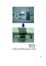
Page 43: ...43 Installing the MSP430 cable to console MSP430...

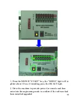
Page 44: ...key the MODE light will to glitter about 10 sec If installing pass the OK LET light 2 Drive the machine to provide power for console and then enter into the engineering mode to confirm if the software...

Reviews: