background image

Version 1.0 2014  IC-MXIC7B-01  Copyright by Indoorcycling Group GmbH 2014  |  www.indoorcycling.com

WARNING!

Please carefully observe the following instructions. The maintenance and care procedures 

must be performed in the regularity set out, to ensure maximum operating safety and lifespan. 

Irregularly observed  maintenance and care procedures will lead to increased wear to the 

product and will void the warranty. If you have any further questions on this topic, please 

contact our technical support.

Please only use the acid- and solvent-free maintenance and care agent (e.g. Brunox) 

recommended by us to prevent damage to components of the indoor cycle.

DAILY MAINTENANCE:

1.

 Make sure that the indoor cycle is leveled and does not rock 

(if necessary adjust as described on p.15).

2.

 Cleaning: The indoor cycle must be regularly cleaned after each use for reasons of hygiene. 

Ensure that there are sufficient soft cloths or paper towels and maintenance and disinfection 

agent available. First disinfect the saddle and handlebars with a suitable agent and then wipe all 

bodily residues off the entire indoor cycle.

WEEKLY MAINTENANCE:

1.

 Cleaning: Depending on how often the indoor cycle is used, it must be extensively cleaned 

once a week. To do this, spray a maintenance spray onto a soft cloth and clean all plastic parts, 

the entire flywheel, exposed framework parts including stabilizers and the plastic casing.  


Never spray the maintenance spray directly onto the flywheel, as this could cause the drive belt 

to slip through (belt slip).

PREVENTIVE 

MAINTENANCE

Summary of Contents for IC-MXIC7B-01

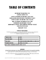
Page 1: ...AND INSTRUCTIONS IN THIS MANUAL BEFORE YOU START USING THIS EQUIPMENT PLEASE KEEP THIS MANUAL FOR FUTURE REFERENCE IMPROPER ASSEMBLY USE OR MAINTENANCE CAN VOID THE WARRANTY TERMS ADDITIONAL LANGUAGE...
Page 2: ...ormance data shown on the display exceeds the requirements according to DIN EN 957 5 for Class A ergometers The average achieved accuracy of 1 relates to a rotational speed range of 40 120 RPM and a b...

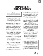
Page 3: ...ctor Use of the bike by persons over the age of 14 only after they are briefed by a qualified trainer or instructor 9 The indoor cycle must not be used by persons exceeding weight of 330 lbs 150 kg 10...

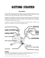
Page 4: ...eturn for minimal maintenance effort This will guarantee long standing interruption free operation Instructions on operation and managing training for the Coach by Color computer can be found in the c...

Page 5: ...site Ifthereareneverthelesslargefluctuationsintemperature pleaseallowthebiketoacclimatisetothesurrounding temperature before proceeding with assembly WARNING Please ensure that bolts are tightened wit...

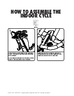
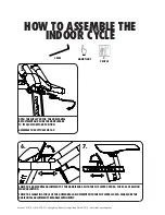
Page 6: ...YCLE 2 PEOPLE 1 2 SET THE VERTICAL ADJUSTMENT OF THE HANDLEBAR STEM TO THE HIGHEST POSITION BEFORE BEGINNING WITH ASSEMBLY DO NOT REMOVE WARNING TAPE FROM THE SLIDERS PRIOR TO THE HANDLEBAR BEING ASSE...

Page 7: ...H SUFFICIENT FORCE 30 NM WHEN MOUNTING THE HANDLEBARS THE FASTENING COUNTER SUNK BOLTS ARE COATED WITH TUFLOK AT THE FACTORY TO PREVENT THEM FROM BECOMING LOOSE DURING USE IF BOLTS ARE LOOSENED AFTER...

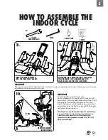
Page 8: ...ORIZONTAL ADJUSTMENT AND SLIDE THE HANDLEBARS TO ITS MOST FORWARD POSITION ASSEMBLE THE BOTTOM END CAP CHECK THE HORIZONTAL ADJUSTMENT OF THE HANDLEBARS WITH THE FLIP LEVER OPENED FOR EASE OF MOTION W...

Page 9: ...ing counter clockwise left hand thread Please make sure that both pedals are fastened with sufficient force 55 NM to ensure that the bolt does not become loose during use The threads are provided with...

Page 10: ...ease 1 Make sure the bike is level If bike rocks on the floor turn the levelling feet underneath the front and or rear stabilizer until the rocking motion is eliminated Make sure that the levelling fe...

Page 11: ...manufacturer authorised service technicians BATTERIES MAY NOT come into contact with fire come into contact with coins or other metallic objects If the device remains unused for an extended period of...

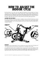
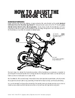
Page 12: ...ps cages on the pedals or in the SPD cleats if you are using cycling shoes if your indoor cycle is not fitted with a combi pedal system HOW TO ADJUST THE INDOOR CYCLE VERTICAL HANDLEBAR ADJUSTMENT WAR...

Page 13: ...rder to avoid injury to the knees Sit on the saddle and move the pedals until the crank arms are in the horizontal position The knee of your forward facing leg should be positioned directly above the...

Page 14: ...d positioning It is recommended to change hand positions frequently during extended workouts in order to minimise one sided and monotonous exertions on your muscles ligaments and joints HANDLEBAR POSI...

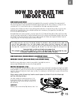
Page 15: ...justment before the wheel is tilted Please take extra care when moving the indoor cycle over uneven surfaces A second person is advisable here to prevent the cycle from tilting to one side Allow a min...

Page 16: ...e sure that the indoor cycle is leveled and does not rock if necessary adjust as described on p 15 2 Cleaning The indoor cycle must be regularly cleaned after each use for reasons of hygiene Ensure th...

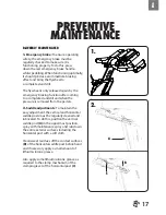
Page 17: ...pressure is removed from the pedals 2 Saddle adjustments To maintain the easy adjustment the vertical and horizontal saddle posts must be regularly cleaned and lubricated To do this position the verti...

Page 18: ...the horizontal post with a soft cloth Clean sweat residues off the contact surfaces of the horizontal handlebar post B beforehand and if necessary apply a small amount of lithium silicone grease Also...

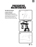
Page 19: ...he easy adjustment of the vertical handlebar and saddle posts it is recommended that you check the clamping mechanism and if necessary apply a small amount of lithium silicone grease to the vertical c...

Page 20: ...NO PRODUCTION CODE OBSERVATIONS ACTION TAKEN RESULT NAME DATE ACTIVITY ROTATION DETAILS FEET LEVELLING DISINFECTION CLEANING OF THE BIKE DAILY P 16 SERVICING BRAKE PADS DETAILED CLEANING OF THE ENTIR...

Page 21: ...VITY AND REQUIRED SCHEDULE BI WEEKLY MAINTENANCE CHECKLIST BIKE NO PRODUCTION CODE OBSERVATIONS ACTION TAKEN RESULT NAME DATE MONTHLY MAINTENANCE CHECKLIST BIKE NO PRODUCTION CODE OBSERVATIONS ACTION...

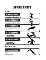
Page 22: ...00004 01 100 01 00006 01 100 01 00009 01 120 01 00005 01 100 01 00007 01 INLAY SLEEVE SET FOR HANDLEBAR TUBE INLAY SLEEVE SET FOR SEATPOST TUBE LEFT FLYWHEEL SUPPORT ARM KIT LOWER SEATPOST ASSEMBLY V...

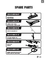
Page 23: ...0 01 180 01 00018 01 180 01 00021 01 COMFORT SPORT SADDLE BLACK RED INCL SADDLE CLAMP SEATPOST GASDAMPER KIT FLIP LEVER ASSEMBLY FOR HORIZONTAL SEATPOST ADJUSTMENT 190 01 00011 01 190 01 00007 01 BOWD...

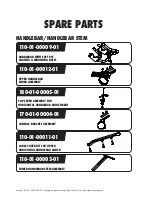
Page 24: ...01 00009 01 170 01 00004 01 110 01 00012 01 110 01 00011 01 110 01 00003 01 180 01 00005 01 HANDLEBAR WITH SOFT PVC COATING MOUNTING BOLTS CONSOLE BRACKET ASSEMBLY UPPER HANDLEBAR SLIDER ASSEMBLY CABL...

Page 25: ...0 01 BOWDEN CABLE SPARE PART KIT FOR VERTICAL HANDLEBAR ADJUSTMENT 180 01 00017 01 190 01 00006 01 HANDLEBAR GASDAMPER KIT END CAP SET FOR HANDLEBAR BRAKE SYSTEM 130 01 00011 01 UPPER BRAKE ASSEMBLY 1...

Page 26: ...1 190 01 00009 01 EMERGENCY BRAKE SPARE PART KIT LOWER EDDY CURRENT BRAKE SPARE PART KIT 190 01 00012 01 190 01 00013 01 BOWDEN CABLE SPARE PART KIT FOR EMERGENCY BRAKE BOWDEN CABLE SPARE PART KIT FOR...

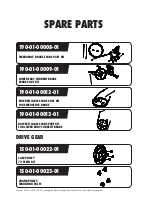
Page 27: ...00044 01 900 00 90008 20 FLYWHEEL AXLE KIT FLYWHEEL SPARE PART ASSEMBLY POLY V BELT 4PK 895 FOR SECONDARY DRIVE CRANK MOUNTING BOLT M8X20X1 25P 150 03 00045 01 150 03 00059 01 POLY V BELT 2PJ 330 FOR...

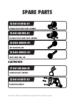
Page 28: ...ling com SPARE PARTS 150 03 00054 01 150 03 00053 01 150 01 00016 01 170 01 00004 01 150 01 00017 01 150 01 00018 01 LEFT CRANK ARM RED RIGHT CRANK ARM RED PRIMARY DRIVE IDLER PULLEY ASSEMBLY CONSOLE...

Page 29: ...00005 01 170 01 00006 01 170 01 00007 01 POWER MODULE PCB ASSEMBLY GEAR MODULE PCB ASSEMBLY PHOTO INTERRUPTER PCB KIT GAMMA SENSOR PCB ASSEMBLY 170 01 00016 01 170 01 00015 01 MAIN CABLE HARNESS SET...

Page 30: ...roup GmbH 2014 www indoorcycling com SPARE PARTS 320 00 00009 01 170 03 00012 01 CONSOLE KIT LIPO RECHARGEABLE BATTERY 5000MAH 3 7V SHROUD 160 01 00004 01 160 01 00006 01 160 01 00007 01 RIGHT SIDE MA...

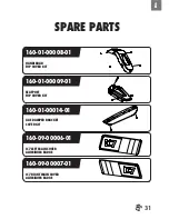
Page 31: ...01 00008 01 HANDLEBAR TOP COVER KIT 160 01 00009 01 160 01 00014 01 SEATPOST TOP COVER KIT GAS DAMPER BRACKET COVER KIT 160 09 00006 01 160 09 00007 01 IC7 LEFT MAIN COVER ALUMINUM BADGE IC7 RIGHT MAI...

Page 32: ...00011 01 160 01 00010 01 MATRIX LOGO PLATE INSERT KIT RIGHT MATRIX LOGO PLATE INSERT KIT LEFT FRONT AND REAR STABILIZER 140 01 00004 01 140 01 00005 01 FRONT STABILIZER PROTECTION PLATE KIT LEFT FRONT...

Page 33: ...RTS 900 10 00003 01 190 01 00004 01 140 01 00006 01 140 02 00006 01 140 02 00002 01 LEVELING FEET RUBBER 75 SHORE STABILIZER MOUNTING KIT REAR STABILIZER STRETCH PLATE KIT FRONT STABILIZER TUBE REAR S...

Page 34: ...Version 1 0 2014 IC MXIC7B 01 Copyright by Indoorcycling Group GmbH 2014 www indoorcycling com SPARE PARTS 150 01 00005 01 150 03 00048 01 COMBI PEDAL SET SPD COMPATIBLE TOE STRAP SET PEDALS...

Page 35: ...mer fitness facility is obligated to maintain and service the product as per the manufacturer s specifications stated in the owner manual of each product 5 YEARS WARRANTY FRAME CONSTRUCTION AND WELDIN...

Page 36: ...Happurger Str 86 90482 Nuremberg Germany EMAIL INFO INDOORCYCLING COM WEBSITE WWW INDOORCYCLING COM 2014 Indoorcycling Group CAUTION READ ALL PRECAUTIONS AND INSTRUCTIONS IN THIS MANUAL BEFORE YOU BE...

Reviews: