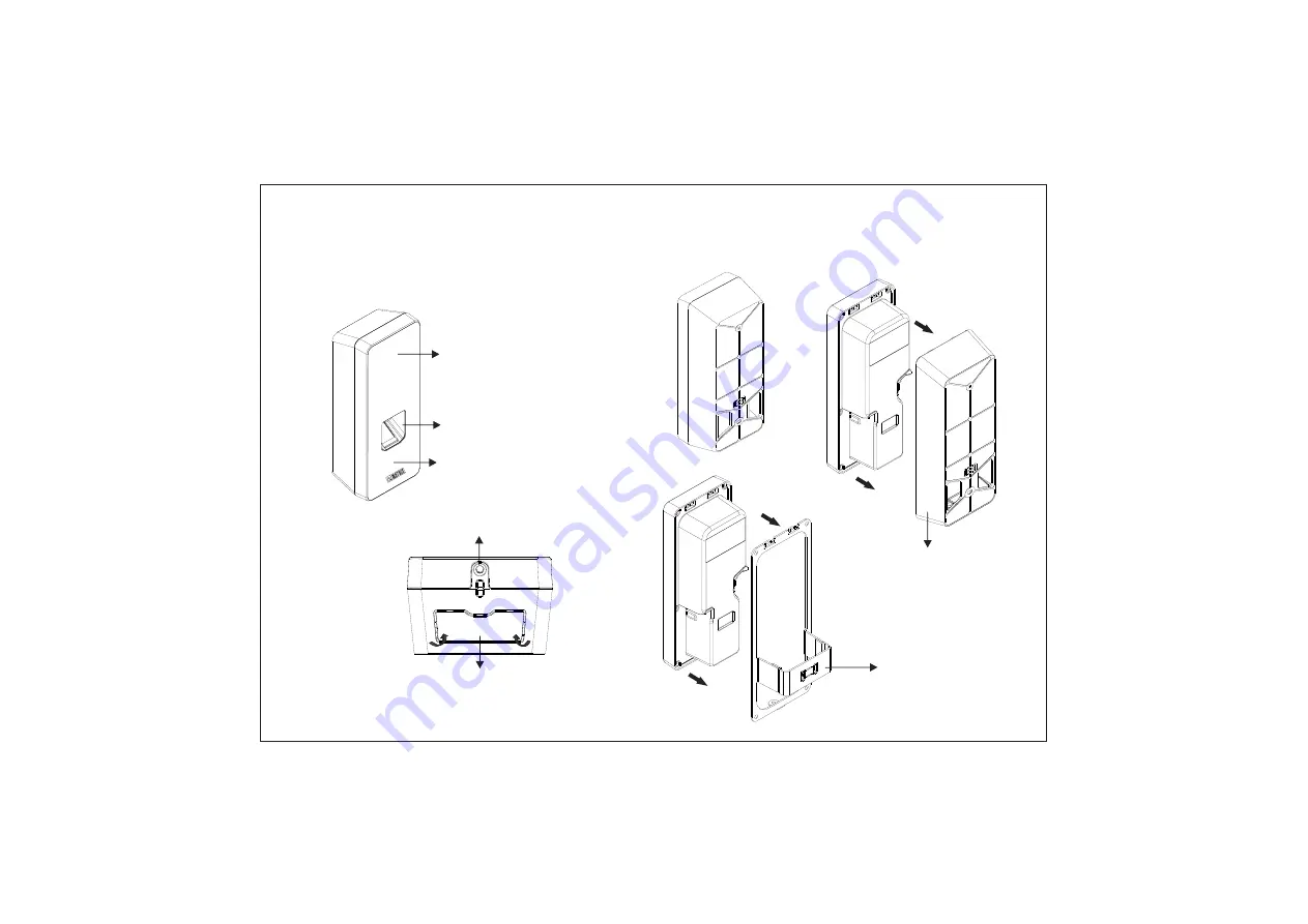
Card Sensing Area
Touch Screen Display
Finger Sensor
Mounting Screw Hole
Figure 1: Front View
Figure 2: Bottom View
Knock Out Area
Know Your COSEC ARGO
Back Plate or Wall Mounting Plate
Figure 3: Rear View
3
4
Flush Mounting Plate
Page 1: ...e of publication However Matrix Comsec reserves the right to make changes in product design and specifications without prior notice Know Your COSEC ARGO 3 8 Preparation For Installation 23 Connecting...
Page 2: ...rea Touch Screen Display Finger Sensor Mounting Screw Hole Figure 1 Front View Figure 2 Bottom View Knock Out Area Know Your COSEC ARGO Back Plate or Wall Mounting Plate Figure 3 Rear View 3 4 Flush M...
Page 3: ...evice You can do indoor installation or on the turnstile under the roof as shown in Figure4 2 You can mount the device on a flat surface such as a wall or Elevator close to the access point door with...
Page 4: ...all mounting or Flush mounting Slide the back plate downwards to unlock the device from the mounting hook and then remove it by pulling it outwards This back plate will be required as Wall mounting pl...
Page 5: ...lution 480x320 pixels HVGA 9 10 Max 12V DC 0 250 A Internal 12V DC 0 5A in PoE supply mode and 12V DC 1A in adapter Specification COSEC ARGO FOE212 COSEC ARGO FOM212 COSEC ARGO FOI212 User Capacity Co...
Page 6: ...Wall Mounting plate with the supplied screws Tighten the screws with screw driver Step 1 Place the Wall Mounting plate and trace screw holes 1 and 2 on the wall where the device is to be installed 1 2...
Page 7: ...f wall mounting plate to fit the wall mounting plate easily with COSEC ARGO 13 14 Connect the cables of the ARGO unit and lead all the cables through the duct of the Wall mounting plate into the elect...
Page 8: ...crew into the mounting screw hole at the bottom of the device Tighten the screw to complete the Wall mounting 15 16 Step 4 Align COSEC ARGO on the mounting plate and hook into the mounting slot Press...
Page 9: ...Step 1 Place the Flush Mounting Template on the desired installation surface Mark the area along the dotted line and trace the four screw holes say A B C D on the wall as shown in Figure7 Now drill th...
Page 10: ...the wall Mounting Slots Mounting Screw hole Step 3 19 Keep all the cables parallel to the side of the COSEC ARGO body in such a way that it should not cover the back of the body as illustrated in bel...
Page 11: ...and hook into the mounting slot Press the bottom side inwards to lock it in place Step 4 Mounting Screw Step 5 Insert the mounting screw into the mounting screw hole at the bottom of the device Tight...
Page 12: ...e mounting surface Make the electrical connections of Power External Reader and EM Lock by connecting supplied cable assembly to the 20 pin connector on the back side of COSEC ARGO 1 2 CN1 Power GND B...
Page 13: ...RMA department The product refered is covered by the waste Electrical and Electronic Equipment WEEE directive and must be disposed of in a responsible manner WEEE Directive 2002 96 EC Disposal Of Prod...
Page 14: ...art of this document may be copied or reproduced in any form or by any means without the prior written consent of Matrix Comsec Warranty Limited Warranty Valid only if primary protection is provided m...