4
P: 1800 281 282
|
F: 1300 281 282
|
|
W: www.matelecaustralia.com.au
User Commands
SMS commands are sent to the phone number of the SIM card installed. This phone number should be supplied with the SIM card.
Commands sent ending with ‘?’ are a query of the command setting, commands sent without this are used to configure the setting.
The symbols < > are used to reference user information to be sent in the commands, and should not be send in the command
message.
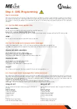
Step 4 - SMS Programming
#title?
4.1 - Set the SMS alarm sender title
Use this command to add the SMS alarm sender title (max 50 characters).
Example SMS command:
#title ME-Link SMS Alarm Sender
The title will be set to ‘ME-Link SMS Alarm Sender’. This will be sent with each alarm message sent from the SMS alarm sender.
#num add <slot> <number>
Use this command to add the phone numbers.
Example SMS Command:
#num add 3 0406446XXX
The phone number 0406446XXX will be added to phone number slot 3.
#num del <slot>
#msg all on?
Use this command to request alarm messages for all inputs in
ON state.
Example response:
Input on messages:
1: Power On/Restored
2: High Level Fault
3: Pump 1 Fault
4: Pump 2 Fault
5: -----------
6: -----------
7: ME-Link Mains Power Failure
8: ME-Link Battery Voltage Healthy
#msg all off?
Use this command to request alarm messages for all inputs in
OFF state.
Example response:
Input on messages:
1: Power Off/Failure
2: High Level Fault Cleared
3: Pump 1 Fault Cleared
4: Pump 2 Fault Cleared
5: -----------
6: -----------
7: ME-Link Mains Power Restored
8: ME-Link Battery Voltage Low
#title <new title>
4.2 - Set the numbers to receive alarm messages
Use this command to delete a phone number
Example SMS command:
#num del 3
The phone number 0406446XXX is deleted from slot 3.
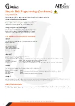
4.3 - View input alarm messages that will be received
Each digital input will send a message when the input turns on (goes high) and when it turns off (goes low). Inputs 7 and 8 are pre-
programmed for power fail and battery voltage low alarms. Inputs 1-4 are pre-programmed to match the outputs privided by the BMS
interface board, so no user programming is required. The default on and off messages for each input are shown below under the
#msg all on?
and
#msg all off?
commands.
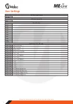
<input>
is the digital input number from 1 to 8 that will trigger the SMS alarm messages.
<message>
Is the text message you want to send to the phone number based on the input state.
<slot>
is the phone book slot from 1 to 10 which phone numbers can be added and deleted from.
<number>
is the phone number assigned to the phone book slot that will receive the alarm messages.
#num?
Use this command to request the phone number list. Empty slots are reported as ----------.
Use this command to enquire the current SMS alarm sender title.


