Single Pump Controller Installation
and Operating Instructions
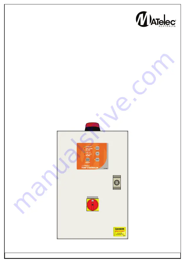
MODEL: FPC-1500
7
-CON
MAIN ISOLATOR
DOC: FPC-1500
VER 1.0
P U M P
C O N T R O L
OWNER’S
OPERATION &
COMMISIONING
MANUAL
Page 1: ...Single Pump Controller Installation and Operating Instructions MODEL FPC 15007 CON MAIN ISOLATOR DOC FPC 15007 CON VER 1 0 P U M P C O N T R O L OWNER S OPERATION COMMISIONING MANUAL ...
Page 2: ...by a suitably qualified Electrician SAFETY WARNING All electrical connections must be carried out by a suitably qualified and registered electrician SAFETY 2 HRH 5 DATA SHEET 7 INSTALLATION 3 CIRCUIT DIAGRAM 10 Mounting Connection NOTES 11 AT A GLANCE 12 Indicators GETTING STARTED 4 Push Buttons Operations Features Your Single Pump Controller reflects the superior quality and attention to detail i...
Page 3: ...A1 PUMP P2 P3 E P1 T1 T2 Therm 12Vdc BRIDGE IF NOT REQUIRED Mounting Frame Wall INSTALLATION CONNECTION MOUNTING 1 Controller enclosure must be mounted in a vertical position 2 Ensure mounting method does not compromise enclosure weather proof rating 3 Ensure access to main isolator is not restricted 4 Ensure cables conduits entering the panel have mechanical protection and that the penetrations a...
Page 4: ... in Manual Mode after 5 minutes the pump will revert to Auto 6 Off High Level Alarm automatically resets upon open circuit of high level input High Level alarm has 15 minute delay On High Level Alarm can only be reset manually High Level Alarm has 5 second delay Mode A Standard Configuration Start Stop High Level operation When the Pump Start input is closed contact triggered the Duty Pump will be...
Page 5: ...cts This run on occurs even if Pressure switch contacts open during this initial period If however run time exceeds 11 seconds the pump will stop immediately upon open circuit occurring If the Pressure Switch Input closes circuit as well as the Low Pressure Switch Input a low pressure timer will begin counting If this condition exists for a period of 60 seconds then both pumps are shut down and th...
Page 6: ...larm will automatically reset once the High Level input opens circuit The controller will also use the alternate High Level Alarm Delay Typically used for Storm Water applications High Level Alarm delay in this mode is 15 minutes Setting this DIP Switch to On will cause the High level Alarm to remain active until the controller is reset The High Level Alarm will use the standard High Level Alarm a...
Page 7: ...ction PUMP UP Function PUMP DOWN Sensitivity adjustable by a potentiometer 5 100kΩ Measuring frequency 10Hz prevents polarization of liquid and raising oxidation of measuring probes Galvanically separated supply voltage UNI 24 240VAC DC Output contact 1xchangeover SPDT 8A 250V AC1 1 MODULE mounting onto a DIN rail Monitoring of two levels Ω Connection Function Device description Tank with monitore...
Page 8: ...sistance Voltage n electrodes Current in probes Time response Max capacity of probe cable Time delay t Time delay after switching on t1 Accuracy Accuracy in setting mechanical Output Number of contacts Current rating Switching voltage Switched voltage Min switched output DC Mechanical life AC1 Electrical life Other information Operational temperature Storing temperature Electrical strenght Operati...
Page 9: ...se a tank made of a conductive material you can use it as probe C In case you require monitoring of one level only it is neccessary to connect inputs H and D and connect them to one probe in this case sensitivity is lowered by half 2 5 50kΩ Probe C can be connected with a protective wire of supply system PE To prevent undesirable switching out output contacts by various influences sediment on prob...
Page 10: ...40N 12V 0V Transformer 12Vac T1 P1 P2 P3 A1 A2 Contactor 18A 240Vac Contactor 1 Strobe Light Buzzer Inline Relay 12Vdc R1 Common Fault BMS Volt Free 1 2 3 4 5 6 O N A1 A2 C D H Conductivity Relay CR1 A1 A2 C D H Conductivity Relay CR2 PROBE INPUT Low Voltage Stop Common Start High 95 96 NC Contact TOL1 Thermal Switch 18 15 NO Contact CR1 1 18 15 NO Contact CR2 1 R1 1 CIRCUIT DIAGRAM ...
Page 11: ...11 NOTES ...
Page 12: ... ALARM ON A high level alarm has been present for the preset time FLASHING A low level alarm is present ON STEADY Pump switched on to run ON STEADY A pump fault overload has occurred FLASHING A prime loss fault has occurred Silences the siren and if held down for 3 seconds clears all faults If selected the LED indicator will confirm if on the particular pump is set to Automatic Pumping Mode Turns ...