background image


Processes 

MIG (GMAW) 

TIG (GTAW) 

STICK (SMAW) 


OPERATORS’ MANUAL


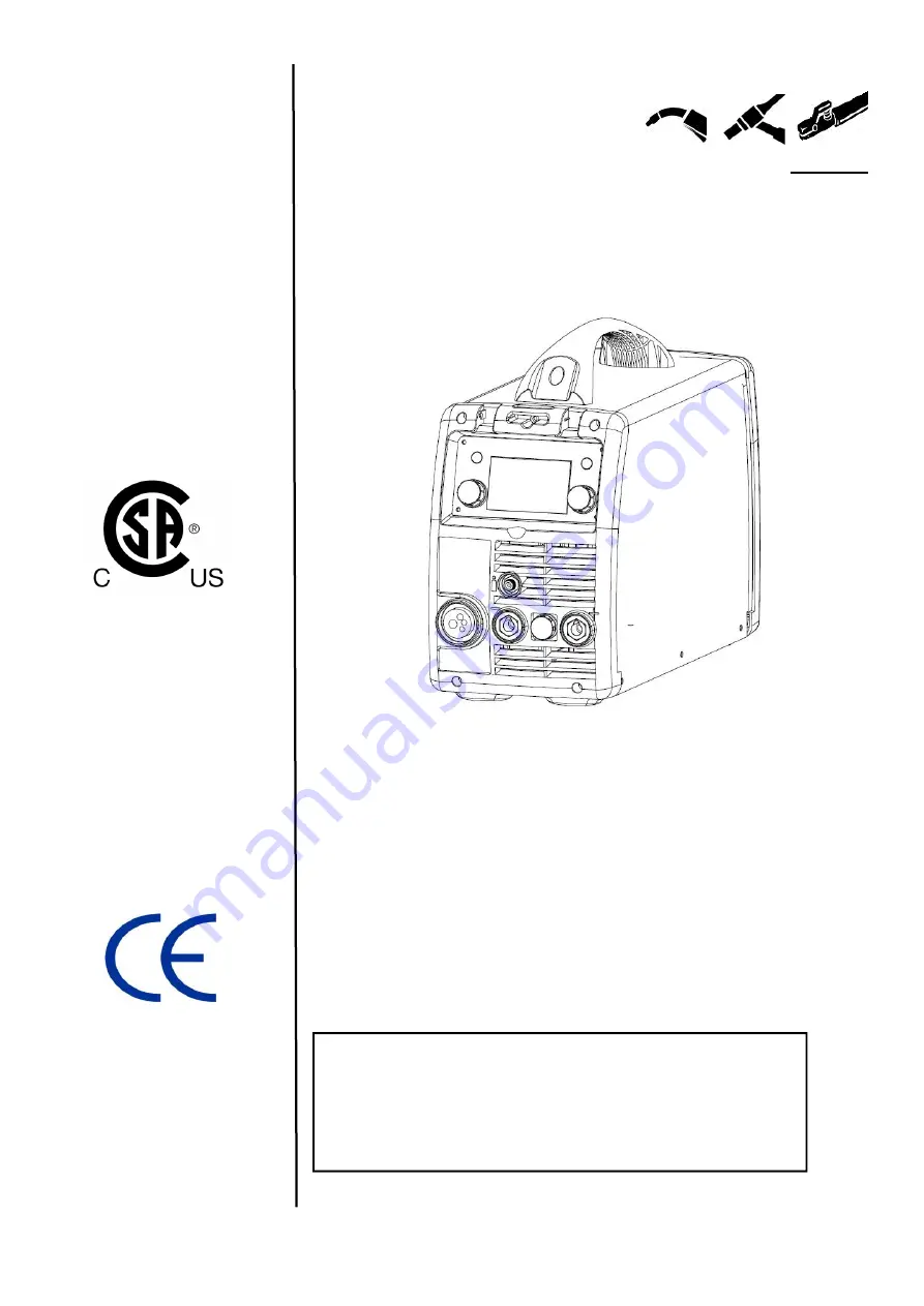
INVERTER MULTMIG WELDER


MM200 LCD 


IMPORTANT: 

Read this Owner’s Manual Completely

 before attempting to use this 

equipment.  Save  this  manual  and  keep  it  handy  for  quick  reference.  Pay  particular 

attention to the safety instructions we have provided for your protection. Contact your 

distributor if you do not fully understand this manual. 


Summary of Contents for MM200 LCD

Page 1: ...ORTANT Read this Owner s Manual Completely before attempting to use this equipment Save this manual and keep it handy for quick reference Pay particular attention to the safety instructions we have provided for your protection Contact your distributor if you do not fully understand this manual ...

Page 2: ...lt Ampere Characteristic 6 3 Installation and Adjustment 7 3 1 Parameters 7 3 2 Duty cycle and Over heat 8 3 3 Equipment Connection 8 4 Operation 9 4 1 Layout for the front and rear panel 9 4 2 Welding operation 10 4 3 Welding parameters 23 4 4Operation environment 23 4 5 Operation Notices 23 5 Maintenance Troubleshooting 25 5 1 Maintenance 25 5 2 Troubleshooting 26 5 3 Maintenance of MIG Gun mech...

Page 3: ...ecause of the DC voltage existing in the electrolytic capacitors ELECTRIC SHOCK CAN KILL Never touch electrical parts Wear dry hole free gloves and clothes to insulate yourself Insulate yourself from work and ground using dry insulation Make certain the insulation is large enough to cover your full area of physical contact with work and ground Take carefully when using the equipment in small place...

Page 4: ...dmium plated steel and other metals or coatings which produce highly toxic fumes keep exposure as low as possible and below Threshold Limit Values using local exhaust or mechanical ventilation In confined spaces or in some circumstances outdoors a respirator may be required Additional precautions are also required when welding on galvanized steel Do not weld in locations near chlorinated hydrocarb...

Page 5: ...mber that welding sparks and hot materials from welding can easily go through small cracks and openings to adjacent areas Avoid welding near hydraulic lines Have a fire extinguisher readily available Where compressed gases are to be used at the job site special precautions should be used to prevent hazardous situation When not welding make certain no part of the electrode circuit is touching the w...

Page 6: ...ks or flame Never allow the electrode or any other electrically hot parts to touch a cylinder Keep your head and face away from the cylinder valve outlet when opening the cylinder valve Valve protection caps should always be in place and hand tight except when the cylinder is in use or connected for use 1 3 Knowledge of Electric and Magnetic Fields HSW SERIES arc welding machine uses Mix gas as sh...

Page 7: ...n MIG Meanwhile the welding current parameter can be adjusted continuously and infinitely to meet with the requirements of welding craft Rectifier Inverter Transformer Rectifier Hall Current Feedback control Single phase AC DC AC DC 220V 50Hz AC DC Welding current regulate Wire feed speed Wire feeder motor PWM signal CPU control Voltage Feedback control 2 3 Volt Ampere Characteristic MM SERIES wel...

Page 8: ...TIG 10 100 MMA 25 200 MIG 10 200 MMA TIG Welding Voltage V 10 27 MIG No load Voltage V 67 MIG 14 TIG MMA Power Factor 0 99 Duty cycle 40 40 140 A 60 115 A 100 90 A 40 100 A 60 85A 100 65 A 40 140 A 60 115 A 100 90 A 40 200A 60 165A 100 130A Diameter mm Fe 0 6 0 9 1 0 Ss 0 8 0 9 1 0 Flux Cored 0 6 0 8 0 9 1 0 Protection class IP23 Insulation class H Cooling AF Dimensions mm 505 210 330 Weight Kg 15...

Page 9: ... and the output current I is shown as the right figure If transformer is over heat the heat relay inside it will open and will output an instruction to circuit board cut AC relay and the output welding current and brighten the over heat pilot lamp in the front panel At this time the machine should be allowed to cool down for 10 minutes with the fan When operating the machine again the welding outp...

Page 10: ...and keep the wire aim at the wire feeder mouth Note The plane of the joint should be aimed at screw plugged tightly and rotated 90º then screw the bolt tightly to ensure the gun contacting closely 7 Connect the shielded gas pipe of torch with the output of front panel on wire feeder 8 Connect the control cable pin of torch with the two lead aero socket of front panel on wire feeder 9 Notice that t...

Page 11: ...et by rotating L Knob 4 System setting interface Rotate R knob to SYSTEM icon A parameter and its corresponding value may be selected and set by rotating L Knob 5 Function icon display interface an interface displaying the icon of the welding method currently used 6 Welding mode icon display interface an interface displaying the icon of the welding mode currently used 2T 4T 7 Synergic parameter di...

Page 12: ...ers 1 In the main interface press the MENU key to enter the synergic parameter selection 2 In the synergic parameter selection interface rotate L Knob to select the required synergic parameters and press it for confirmation in the interface shown below 3 Selection and setting of welding parameters 1 In the main interface press the MENU key to enter the welding parameter setting interface 2 In the ...

Page 13: ... 4T Burn Back 0 10 Slow Feed 0 10 Pre flow 0 2 S Post Flow 0 10 S Inductance 0 10 Fig 2 4 Selection of system setting parameters 1 In the main interface rotate the R knob to parameter setting interface 2 Rotate L knob to select system settings 5 Setting of welding current and voltage 1 Press the ENTER key to enter the welding interface shown below ...

Page 14: ...od 1 In the main interface press the MENU key to enter the function selection interface 2 In the function selection interface rotate L Knob to select the MIG MAG Manual welding method and press down it for confirmation as shown in Fig 1 3 In the wire cabinet confirm Selection Switch is turn down to activate wire feed drive 2 Selection and setting of welding parameters 1 In the main interface press...

Page 15: ...otate L Knob to set the wire feed rate 1 5 13 0 m min and rotate R Knob to set the welding current 10 27 V 3 After the settings press L Knob and R Knob for confirmation 4 Selecting spool gun operation 1 Install spool gun into Gun socket and set Switch to Spool Gun ...

Page 16: ... the MENU key to enter the welding parameter setting interface 2 In the welding parameter setting interface rotate L Knob to select the parameter as required and rotate R Knob to set a value for the parameter afterwards press L Knob or R Knob for confirmation as shown below Welding parameters available by rotating L Knob Welding parameters available by rotating R Knob Hot Start 0 10 Arc Force 0 10...

Page 17: ...er the welding parameter setting interface 2 In the welding parameter setting interface rotate L Knob to select the parameter as required and rotate R Knob to set a value for the parameter afterwards press L Knob or R Knob for confirmation as shown below Welding parameters available by rotating L Knob Welding parameters available by rotating R Knob Two four Stroke 2T 4T Pre flow 0 2 S Down Slope 0...

Page 18: ...ect a welding method as required and press L Knob two times to directly enter the welding interface 4 3Welding parameters Material Wire diameter mm GAS Welding current A Fe metal Solid cored 0 6 CO2 25 90 Fe metal Solid cored 0 8 CO2 40 150 Fe metal Solid cored 0 9 CO2 50 180 Fe metal Solid cored 1 0 CO2 60 200 Fe metal Solid cored 0 6 MIX 25 110 Fe metal Solid cored 0 8 MIX 40 180 Fe metal Solid ...

Page 19: ...ust acid corrosive gas in the surrounding air or substance can not exceed normal standard Take care that there is sufficient ventilation during welding There is at least 30cm free distance between the machine and wall 4 5 Operation Notices Read 1 carefully before attempting to use this equipment Connect the ground wire with the machine directly and refer to 3 5 Ensure that the input is single phas...

Page 20: ...diately If the fan does not rotate after the arc welding machine is overheated observe that whether there is something blocked in the blade if it is blocked please get rid of If the fan does not rotate after getting rid of the above problems you can poke the blade by the rotation direction of fan If the fan rotates normally the start capacity should be replaced If not change the fan Observe that w...

Page 21: ...hine you can consult the following Chart NO Troubles Reasons Solution 1 Close the breaker but the power light isn t on Breaker damaged Change it Fuse damaged Change it Power damaged Change it 2 After welding machine is over heat the fan doesn t work Fan damaged Change it The cable is loosen Screw the cable tightly 3 Press the gun switch no output shielded gas No output gas when test gas No gas in ...

Page 22: ...ol circuit damaged Check the circuit 6 Welding stops and alarm light is on Machine has self protection Check over voltage over current over temperature lower voltage and over temperature and solve it 7 Welding current is run away and can be not controlled The potentiometer damaged Check or change it The control circuit damaged Check the circuit 8 The crater current can be not adjusted The PCB dama...

Page 23: ...stol blow compressed air through the wire guide Blow the wire feed mechanism and reel housing clean with compressed air Reattach the welding gun s parts Tighten the contact tip to spanner tightness 3 Changing the wire guide If the wire guide is too worn or totally clogged change it to a new one according to the following instructions Open the mounting nut of the wire guide which exposes the end of...

Page 24: ...MAINTENANCE AND TROUBLESHOOTING Ⅳ 5 3 2 Parts Breakdown for the MIG gun ...

Page 25: ...with a compact WP17 air cooled TIG torch rated 60 duty cycle 150 amps 30 200A with 12 5 direct connect welding cable cover assembly with Dinse power plug and 5 8 18RHM gas line fitting For extended duty cycle operation or for higher power rated air cooled or water cooled torches contact your Dealer ...

Page 26: ...521 0128 Spool holder 9 521 0109 Front frame 29 521 0129 Gas Feed switch 10 521 0110 Front panel 30 521 0130 Spool or Remote switch 11 521 0111 Installation plate of panel 31 521 0131 MULTIMIG200 power board 12 521 0112 Front panel cover plate 32 521 0132 160 Support rod 13 521 0113 Knob 33 521 0133 Cooling Fan 14 521 0114 Gas out connector 34 521 0134 1225 fan cover 15 521 0115 Female torch conne...

Page 27: ...12 0014 Electrode Holder Cable Dinse 200A with 4GA cable and male connector 526 0026 Gas Hose w single fitting 3 Gas hose with one 5 8 18 nipple fitting 721 0004 Shield Gas Regulator Dual gauge CGA580 IN 5 8 18 nipple SR17 12 2D 9P TIG Torch w Cable 12 5 17 TIG Torch with 12 5 cable and Dinse TGFP250 Foot Pedal Control Foot pedal TIG control with 9 pin cable 16 AK 2 TIG Torch Consumable Kit Assort...

Page 28: ...MAINTENANCE AND TROUBLESHOOTING Ⅳ 5 5 Electrical schematic drawing ...

Reviews: