AU SUPPORT 1800 237 425 WWW.MATCHMASTER.COM.AU | NZ SUPPORT 0800 237 425 WWW.MATCHMASTER.CO.NZPAGE | 3 OF 6
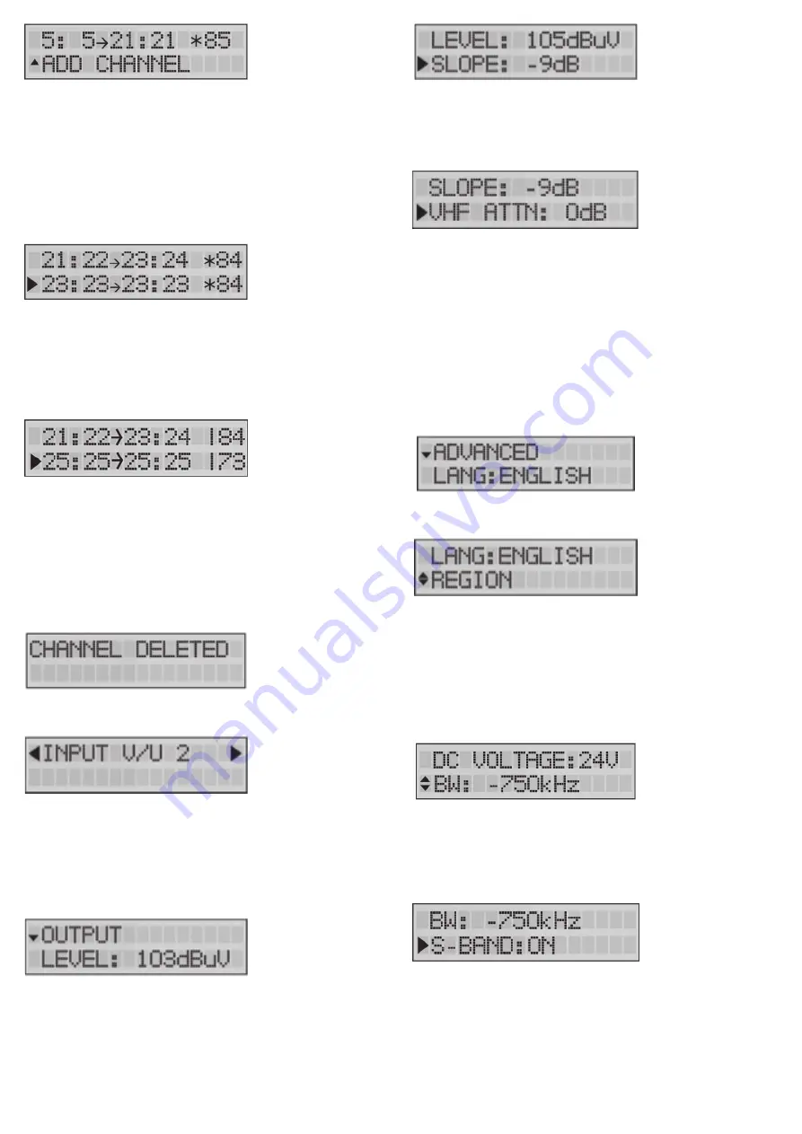
A SLOPE of up to -15dB can be set between the beginning
of BIII and the end of UHF to compensate for cable losses.
0dB means all channels have the same output level (see
previous display readout), -15dB means the beginning of BIII
(174MHz) is 15dB weaker than the end of UHF.
Define the OUTPUT LEVEL of the output signal. Range
between 98dB
µ
V and 118dB
µ
V (default output level is
108dB
µ
V). Check the output via a network analyser on
the -30dB test port. Note: The more channels you select,
the less input power you should give (e.g. 111dB
µ
V for 10
channels).
To delete a (pair of) channel(s), position the arrow on the
channel and press the rotary button 3 seconds.
When you have added all the channels to INPUT V/U 1, and
you want to add channels to the other inputs, scroll up to
the top of the menu (to INPUT V/U 1), tap the button and
scroll to the next input.
Repeat the previous steps for all input channels.
Output Settings
To add another (group of) channel(s), scroll down to ADD
CHANNEL and tap to confirm.
To prevent bad quality or scrambled images, make sure that
only one input channel is assigned to one output channel. If
2 channels are assigned to the same output channel, a star
(*) will appear.
The same applies for adding multiple channels. Make sure
that each output channel is selected only once.
After this, the correct LTE filter will be set for the UHF
inputs (possible filters are 694MHz, 790MHz or OFF). If the
channels are lower than 48, the 694MHz filter is activated.
The 790MHz filter is activated for the channels lower than
60.
Delete a (pair of) Channel(s)
Note 1: The value 85dB
µ
V (in the bottom right corner)
indicates the incoming level of the channel.
Note 2: For EU, Italy and New Zealand region, Channel 13
(230-240MHz) can be used. CH13 cannot be converted.
Note 3: A star (*) will appear when converting to a different
channel bandwidth: e.g. from a 7MHz channel to an 8 MHz
channel
For optimal performance we recommend to only add single
channels, unless you need to process a lot of channels.
VHF ATTN: To compensate for cable losses, an attenuator
of up to 15 dB can be configured to decrease the VHF (up
to 300MHz) and DAB output level (compared to the UHF
output level (above 300MHz)).
Note: In the OUTPUT menu, you define the output level in
dB
µ
V of the MUX’s. The Profiler Revolution has enough gain
to guarantee this output level under all input conditions.
In case a slope has been set, the output level indicated on
the display will be the output level of the highest frequency
MUX.
Advanced Settings
The language of the Profiler Revolution can be set to
English, Italian, Spanish or French.
Tap REGION to check to which region/country the Profiler
Revolution is set. To change the region/country, a hard reset
is required. (see region/country settings)
Define DC VOLTAGE for the inputs, choose between 12V
or 24V. This is a global setting for all inputs, each input can
then be switched between OFF or this value. All countries
are set by default on 24V, except UK which is set by default
on 12V.
The filter bandwidth can be changed from -2000 kHz to
0 kHZ in steps of 250 kHz. This allows you to optimize
the bandwidth of your filter. For instance, a European 8
MHz channel can be changed from 6 to 8 MHz. The default
setting is -750 kHz, which is an optimal setting in 95% of the
cases.
S-Band channels can be activated in Advanced Mode. By
default, they are not activated.
See NOTE below for more explanation.


