


www.masterweld.co.uk
ATTENTION
Machine damage can be caused by improperly connected
coolant lines!
In the case of improperly connected coolant lines or if a gas-cooled
welding torch is used, the cooling circuit is interrupted and machine
damage may occur.
•
Connect all cooling lines properly!
•
Complete the hose package and the torch hose package.
•
Pay attention to the maximum hose package length!
•
If using a gas-cooled welding torch, disconnect the cooling unit
at the rear of the machine.
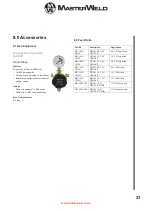
5.8 Gas Testing
•
Open the gas cylinder valve slowly.
•
Open the pressure reducer.
•
Switch on the power supply from the main switch.
•
Press the gas test function on the wire feeder.
•
Adjust the amount of gas in the flow meter according to
the application.
•
The gas test is activated by briefly pressing the button on the wire
feed unit. The shielding gas flows for about 25 seconds or until
the button is pressed again.
Setting the amount of shielding gas welding method recommended
amount of shielding gas
MAG welding Wire diameter x 11.5 = l / min
MIG brazing Wire diameter x 11.5 = l / min
MIG welding (aluminium) Wire diameter x 13.5 = 1 / min
(100% argon) Gas nozzle diameter in TIG mm is equal to 1 / min
gas flow
Incorrect protective gas adjustment!
A too low or too high a shielding gas setting can cause air to reach
the welding pool, resulting in the formation of pores.
•
Adjust the shielding gas amount according to the welding task!
Source information display.
The “Parameter selection” keys are located on the left and right of
the machine control unit. These keys are used to select the source
parameters shown.
Each time the button is pressed, the display changes to the next
parameter (the LED's next to the key indicate the selection). Once
the last parameter is reached, the first parameter is restarted.
The following are shown.
•
Nominal Values (Before welding)
•
Actual Values (During welding)
•
Hold values (After welding)
5.9 Changing Drive Roll Sets
1. Turn off the power source.
2. Release the pressure on the idle rolls by swinging the adjustable
pressure arm down. Lift the cast idle roll assembly and allow it to
sit in an upright position.
3. Unscrew the plastic knob retaining the lower grooved drive roll
and side off the drive roller
4. Ensure the wire size marked on the side of the feed roller
matches the wire size to be used.
5. Replace the drive rolls in reverse of the above procedure
ensuring the wire size to be used is marked on the outward facing
side of the roller as it is refitted.
NOTE:- Be sure that the torch liner and contact tip are also
sized to match the selected wire size.
5.10 Welding Wire Installation
As a factory delivery, the Euro connection is equipped with a
capillary tube for welding torches with spiral liners. If a welding torch
with plastic liner is used the capillary tube should be removed.
•
Use a steel guide tube to weld hard, unalloyed wire electrodes
(steel).
•
Use a chrome nickel guide spiral to weld hard, high-alloyed wire
electrodes (CrNi).
•
Use extension of torch liner for welding or soldering soft wire
electrodes, high-alloy wire electrodes or aluminium materials.
Preparation for connecting welding torches with manual spirals:
•
Check that the central connection is seated in the capillary tube!
Preparations for the connection of welding torches with torch liner
extension.
•
Push the capillary tube forward in the direction of the central
connection by the wire feed and remove it here.
•
Shorten the liner extension just before the wire feed roller with the
a knife.
•
Loosen the centre socket of the welding torch and pull it out.
•
Clean and sharpen the separated end of the wire liner
•
Open the wire drum cover by pulling down and out on the bottom
of the cover
•
Unscrew the plastic retaining wheel from the end of the spool
holder shaft.
•
Position the wire spool so that it will rotate in a direction when
feeding so as to be dereeled from the bottom of the coil.
•
Slide the wire spool all the way onto the shaft and refit the plastic
retaining nut.
NOTE:- There is a friction brake on the reel hub assembly,
to prevent the wire spool over running. When welding stops
ensure the nut is slackened to the minimum setting. It can be
adjusted by means of the nut visible when the plastic nut is
removed.
•
Turn the Spool until the free end of the electrode is accessible.
While securely holding the electrode, cut off the bent end and
straighten the first six inches. (If the electrode is not properly
straightened, it may not feed properly through the wire drive
system. Manually feed the wire from the wire reel and through the
wire guide and then over the top of the wire feed rollers (ensure
the pressure arms are in the raised position).
•
Continue to feed the wire through the outlet guide until 20mm of
wire is protruding from the front of the machine torch connector.
•
Re-position the adjustable pressure arms to there original position
to apply pressure. Adjust pressure as necessary.
NOTE:- The pressure arm should be adjusted in order to give
the minimum amount of pressure on the wire to allow reliable
feeding.
10