


17/03/2014 v2.2
ENGLISH
0
−
The groove must feature a "U" profile for soft materials
(Aluminium and its alloys, CuSi3).
−
The groove must be "V" shaped for harder materials (SG2-SG3,
stainless steels).
−
Rolls with a knurled groove profile are available for flux-cored
wire.
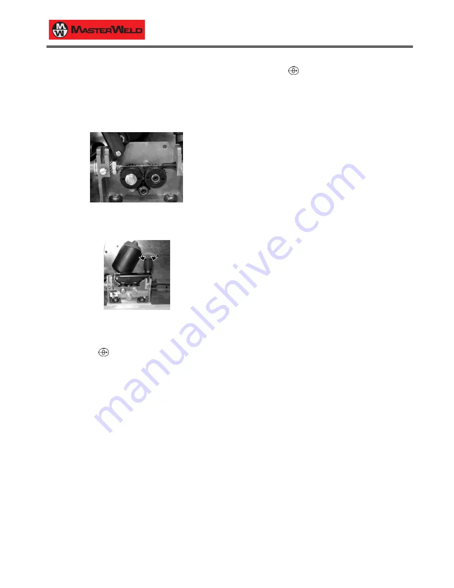
5.
Feed the wire between the wire feeder rolls and insert it into the
MIG/MAG TORCH connector plug.
6.
Make sure the wire is located correctly in the roll grooves.
7.
Close the wire feeder pressure arms.
8.
Adjust the pressure system so that the arms press the wire with a
force that does not deform it while also ensuring constant feed
rate without slipping.
9.
Refit the protective cover.
10.
Set the welding power source ON/OFF switch to “I” (
unit
powered).
11.
Feed the wire through the torch until it protrudes from the tip,
pressing button
on the unit front panel.
4.5
CONNECTIONS TO SOCKETS
1.
Set the welding power source ON/OFF switch to “O” (unit de
-
energized).
2.
Plug the power cable plug into a mains socket outlet.
3.
Connect the gas hose from the welding gas cylinder to the rear
gas socket.
4.
Open the cylinder gas valve.
5.
Connect the power supply cable of the cooling unit to the auxiliary
power socket on the power source.
6.
Attach the coolant hoses to the relevant connectors on the cooler
and on the power source rear panel.
7.
Connect the MIG/MAG torch plug to the EURO TORCH welding
socket.
8.
Attach the coolant hoses of the MIG/MAG torch to the relevant
connectors on the power source front panel.
9.
Connect the plug of the ground clamp to the welding socket on the
basis of the polarity required.
10.
Connect the earth clamp to the workpiece being processed.
11.
Set the welding power source ON/OFF switch to “I” (unit
powered).
12.
Feed the wire through the torch until it protrudes from the tip,
pressing button
on the unit front panel.
13.
Select the torch trigger procedure on the user interface.
14.
Press the torch trigger with the torch well clear of any metal parts.
This serves to open the gas solenoid valve without striking the
welding arc.
15.
Use the flow control valve to adjust the flow of gas as required
while the gas is flowing out.
16.
Set the required welding parameter values on the user interface.
17.
On connecting and enabling a remote controller [RC] certain
settings can be modified from said controller without having to
take action on the user interface of the welding power source.
The system is ready to start welding.
MIG/MAG installation
Summary of Contents for 321 HDP
Page 1: ...17 03 2014 v2 2 ENGLISH 0 MasterWeld 321 HDP Instruction manual GB...
Page 2: ...17 03 2014 v2 2 ENGLISH 0...
Page 8: ...17 03 2014 v2 2 ENGLISH 0...
Page 22: ...17 03 2014 v2 2 ENGLISH 0 22 30 15 SPARE PARTS 15 1 321 HDP...
Page 24: ...17 03 2014 v2 2 ENGLISH 0 24 30 15 2 WIRE FEEDER MOTOR...
Page 26: ...17 03 2014 v2 2 ENGLISH 0 26 30 16 ELECTRICAL DIAGRAM 16 1 321 HDP...


