


TROUBLE SHOOTING
36
Copyright © 2008 Mastervolt / December 2008 / WHISPER 15 ULTRA - Three Phase / US
5.4
SPECIAL PROCEDURES ENGINE
5.4.1
Setting the RPM
RPM is set by the manufacturer and should not need
readjustment! When adjustments are necessary this can
only be done with the help of an interface to a computer
and special software to get access to the microprocessor.
If readjustment of the RPM is necessary, please contact
your Mastervolt Service Centre for advice:
5.4.2
Adjusting valve clearance and
retightening the cylinder head bolts.
Both procedures have to be carried out with a cold engine.
When both procedures are carried out be sure to retighten
the cylinder head bolts before adjusting the valve
clearance. When retightening the cylinder head bolts,
drain the coolant by removing the drain plug (refer. to fig. 3
– 6).
Loosen the bolts slightly, remove the rocker assembly (the
rocker arms, shaft, and stays) and then retighten the bolts
to the specified torque in the numerical order illustrated
(ref. to fig. 26).
Tightening torque cylinder head bolt:
88 ± 5 Nm
Rocker stay tightening torque:
14.7 ± 2 Nm
Figure 26: Cylinder head bolts
The clearance of both (intake and exhaust) valves should
be 0.25 mm in cold condition. Set the piston of the first
cylinder to be adjusted to top dead centre (T.D.C.) of
compression stroke.
The T.D.C. of compression stroke can be found by
aligning the T.D.C. mark (notch) on the crankshaft pulley
with the mark on the gear case (ref. to fig. 27).
Figure 27
First align the T.D.C. mark for the No. 1 cylinder. Confirm
that the valves do not move up or down when the
crankshaft is turned about 20 degrees in normal and
reverse direction of rotation.
If the rocker arms move piston no.1 is on the T.D.C. of the
intake or exhaust stroke. In such case turn the crankshaft
360° in the direction of engine rotation again. No. 1 piston
is now at T.D.C. of the compression stroke.
After adjusting the valves of cylinder 1 adjust the valve
clearance of the remaining cylinders in firing order 1 – 3 –
4 – 2. Turn the crankshaft 180 degrees clockwise from the
T.D.C of cylinder 1 to the T.D.C of cylinder 3. and turn the
crackshaft 180 degrees further clockwise to the TDC of
cylinder 4 and adjust the valves. And again 180 degrees to
adjust cylinder 2.
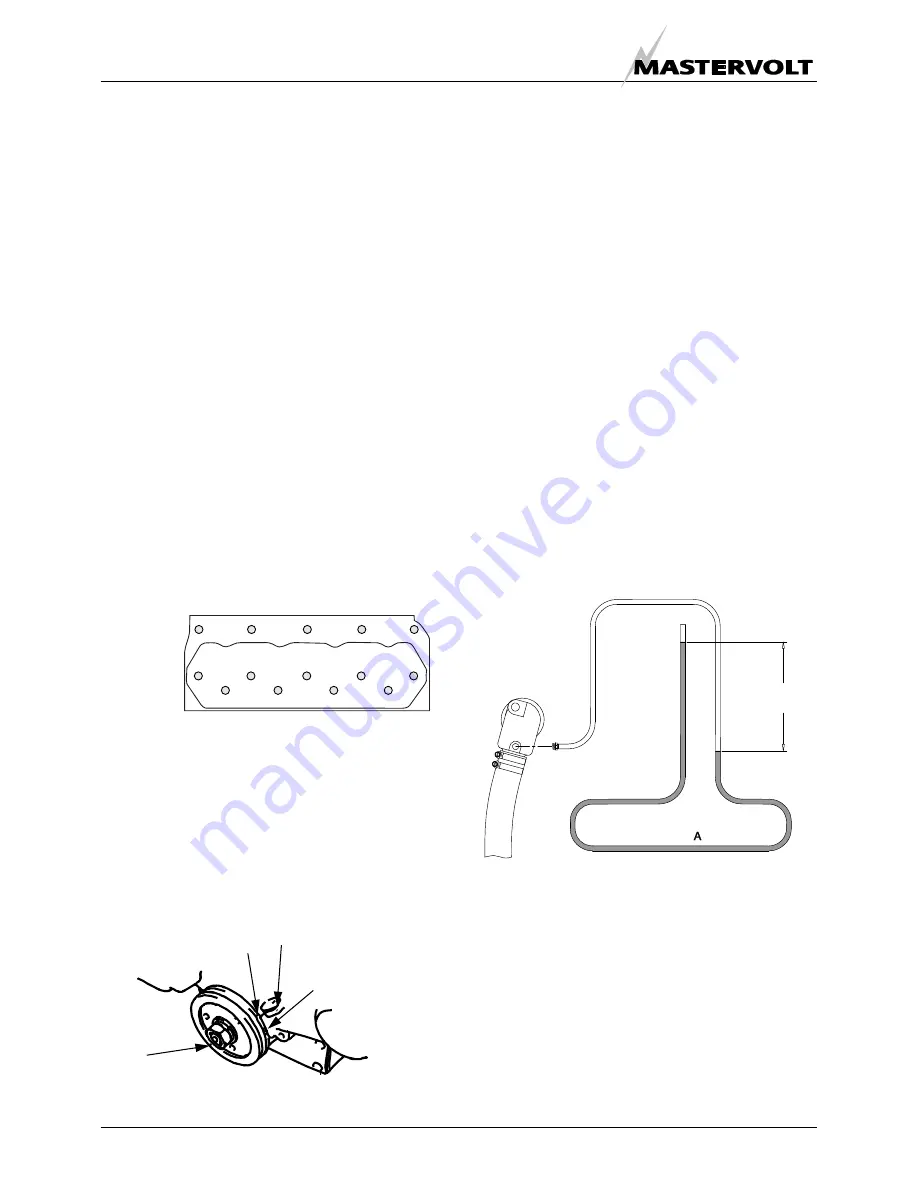
5.4.3
Measuring exhaust backpressure
The exhaust system must be of adequate size -2”/ 51 mm
- and maximal length (refer to installation manual). When
any doubt; backpressure has to be measured. An easy
way to measure for back-pressure is to use a water
column.
A water column can be made visible in a plastic tube along
a yardstick and fitting the end to a hose connection to fit in
the adaptor on the injection bent after removing the
exhaust temperature switch.
Fig 28: Measuring exhaust backpressure
The bent A hanging down should not be too short helping
to damp the pulsating effect of the gas discharge that is
characteristic for a one cylinder engine. The water column
should be no more than 27 inches (69 cm.) of water (1 PSI
- 0,07 bar)
Mark on timing gearcase
IT (injection timing)
mark
TDC mark piston 1 and 4
TDC mark piston
2 and 3
10
4
2
5
7
8
6
1
3
9
14
12
1
13
1
FRONT
MOTOR
MAXIMUM
69cm
27INCHES