


OPERATION
9
By holding the POWER switch pressed again for approx. 3
seconds, the Chargemaster will switch back to stand-by:
the Chargemaster stops and the POWER switch
illuminates orange.
WARNING
Switching the Chargemaster to “stand-by”
does not cut off the connection to the batteries
or the AC-source. This means that voltages
are still available inside the apparatus.
If the Chargemaster was switched to stand-by or AC
power became unavailable, the POWER switch starts to
blink orange. After approximately 2 minutes the blinking
will stop and the display will switch off, so that the batteries
will not be loaded by the indication light.
Only if DIP-switch #3 was adjusted to ON
and
the charger was switched on, the indication
light stays blinking orange, indicating that the
AC-power supply fails in operation. Note that
this blinking LED may slowly drain your
batteries.
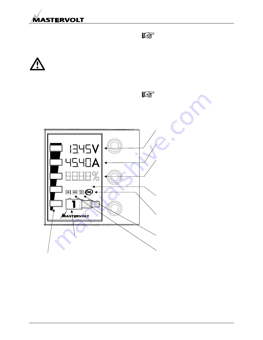
3.3 LCD-DISPLAY
The display at the front side of the Chargemaster enables
you to monitor the charging process. See figure 3.
If no switch is touched during 20 seconds, the
display will go to the initial readings, showing
the charge voltage and charge current.
Figure 3: Initial readings at the LCD-display (displayed values may differ)
Actual charge voltage (Volts).
Actual charge current (Amps).
Battery capacity in %.
Only displayed when the Chargemaster is
connected to a MasterShunt by means of
the MasterBus network (see chapter 6).
This readout shows the actual amount of
energy that is in the battery.
Selected battery bank (1, 2 or 3).
Press SOURCE to alter.
Highlighted if the Chargemaster is
connected to the Masterbus network.
Highlighted if a failure was detected
See section 3.8.
SOURCE
INFO
POWER
CHARGEMASTER
FLOAT
ABS
BULK
FAILURE
Highlighted if AC voltage is not
available.
Actual stage of the Three Step charge
algorithm. See section 3.4.
Hours and minutes indication.