background image

18

Installing and Adjusting Router Bit

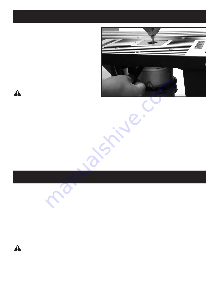
Adjust height of router bit so that it falls flush to table.

Adjusting the Fence Facing:

• The fence facings control the width of the opening beside the router bit. They are mounted on the front face of

the router table fence. Loosen the hand knobs on the back of the fence to adjust the fence facings to fit your

project, then tighten them securely when the facings are positioned correctly. 

• Securely tighten the fence with the hand knobs when positioned correctly. The fence can also be adjusted

forward or backward a distance equal to the amount of material to be removed by the router bit To adjust

loosen the two hand knobs on the back of the fence on either the left or right side and slide the fence forward

and backward to desired position.

WARNING:

Do not operate the router if any part of the router bit contacts the overhead or the right and left fence facing 

Using the Router Table

Installing the Router Bit

1. Make sure the router bit is the right size for

your router.

2. Install the bit so that the router collet engages

3/4" (19,05mm) of the router bit shank.

3. If the shank of the router bit bottoms out in

the collet, back out the router bit

approximately 1/16" (1,59mm) to allow for

proper tightening.

WARNING:

Never install router bits with less than 3/4" 

(19,05mm) of shank engagement in the collet.

Adjusting the Router Bit

1. Using a scrap piece of wood the same height as the work piece, raise and lower the router until the top of the

router bit cutting edge lines up with the top of the scrap wood. (Refer to your 

Router Owner’s Manual

for

instructions on how to adjust your particular brand of router.)

2. Make sure the router is securely tightened in the router base.

3. Check that the router bit is securely tightened in the router chuck.

4. Remove the board from the fence and lower the overhead guard down to the operating position.

Summary of Contents for 480410

Page 1: ...s for future reference If you encounter any problems or difficulties please do not return this product to the store Please contact our toll free customer service department at 1 800 423 3598 1 310 522...

Page 2: ...Router 11 Table 1a Metric For Installing the Router 12 Installing the Adaptor Plate 13 15 Attaching Router Power Cord to the Switch Box 16 Operating the Switch Box 17 Installing and Adjusting Router...

Page 3: ...Keep hair clothing and gloves away from moving parts Be sure switch is OFF before plugging in Remove adjusting keys and wrenches before turning the tool ON Do not overreach Make sure your body is bala...

Page 4: ...the function of the guard before each use Remove all dust chips and any other foreign particles that can affect its function Router Table Power Tool Table Use and Care Do not use this product until al...

Page 5: ...the router table for any reason when the router is running except to turn it OFF Before making any cut make sure the router is turned OFF the router bit is not rotating and the power cord is unplugge...

Page 6: ...6 Parts Make sure all parts pictured below are included in package...

Page 7: ...ong flat countersunk head machine screws Three 10 32 x 1 2 12 7mm long flat countersunk head machine screws Three 1 4 20 x 1 1 4 6 35mm x 31 75mm long flat countersunk head machine screws and three 1...

Page 8: ...e hole on the table is in comparison to the outlet box Product 3 These fasteners will be used for the majority of fastening of the router table Use these fasteners in this order for optimal fastening...

Page 9: ...ver Table should look like this 6 Fence Assembly Instructions Using the smallest carriage bolts fasten fence face plate to table bracket fence Use washers and knobs as shown 1 Fasten fence face plate...

Page 10: ...edium and one long Use the medium one on hole 1 and long one on hole 2 See completed 4 1 2 1 2 Insert pin into chip guard and fence bracket as shown 5 OPTIONAL Use holes on the bottom of table legs to...

Page 11: ...yobi R175 2 11 32 Two 5 16 18 x 5 8 Long Flat Base Plate Not Removed Countersunk Head Screws Screws Only Ryobi RE175 2 11 32 Two 5 16 18 x 5 8 Long Flat Base Plate Not Removed Countersunk Head Screws...

Page 12: ...y Ryobi R175 2 8 7mm Two 7 9mm x 15 9mm Long Flat Base Plate Not Removed Countersunk Head Screws Screws Only Ryobi RE175 2 8 7mm Two 7 9mm x 15 9mm Long Flat Base Plate Not Removed Countersunk Head Sc...

Page 13: ...35mm Shaft through paper template into collet of router 2 Using the template and router base locate and mark the center of router plate retaining screws 3 Using the punch make hole through the templa...

Page 14: ...retaining screws 8 Using Table1 1a pg 11 12 drill the correct hole size on all marked spots 9 Using 3 4 19 05mm dia x 81 steel countersinking tool countersink all holes 10 Remove router base plate if...

Page 15: ...llation of a countersunk screw The countersunk screw must be flush or below the top of the adapter plate If the screw protrudes above the adapter plate the adapter plate may not properly seat against...

Page 16: ...the wall socket without stretching 5 Plug the power cord from an accessory you will be using such as a wet dry vac or light into the other outlet 6 Plug the power cord from the router into the electr...

Page 17: ...ke sure the router table is secure when not in use 1 Flip the switch box lever to the OFF position and remove the safety key 2 Unplug the switch box power cord from the electrical outlet 3 Turn the ro...

Page 18: ...router bit contacts the overhead or the right and left fence facing Using the Router Table Installing the Router Bit 1 Make sure the router bit is the right size for your router 2 Install the bit so t...

Page 19: ...the fence assembly To prevent this the router table fence assembly has a port in the back where a wet dry vac hose up to 2 1 2 6 35cm in diameter can be connected Just hold the router table fence ass...

Page 20: ...r bit has been removed from the router Routing Using the Fence 1 Set the speed control to the required speed if you are not sure of the correct speed experiment until you find a speed that creates the...

Page 21: ...21...

Page 22: ...22...

Page 23: ...23...

Page 24: ...24...

Reviews: