Operating Instructions:
This unit can be operated with the engine on or off.
It operates like any other battery powered tool drawing power from
the battery. Its performance will vary with the battery’s state of
charge. Actual operating time available with the engine off will vary
depending on your battery’s size, age, temperature and state of
charge. Typically with the engine running the charging system will
provide slightly more voltage to the unit thereby increasing the unit’s
performance.
Unpack the unit and completely un-wrap the power cord and inspect
for damage.
Place the unit on a dry, level surface.
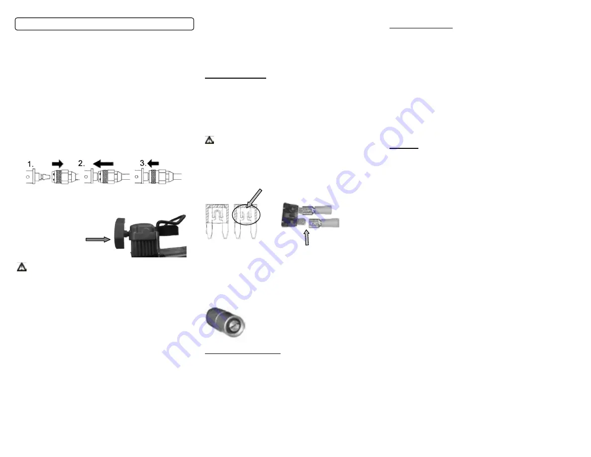
Connect the air supply hose to the unit using the quick connect
fitting as shown in Fig. 3 below.
1. Slide the retaining snap ring back.
2. Slide the fittings together firmly.
3. While holding fittings together firmly slide the outer ring forward to
lock . See image below.
4. Install the red air filter housing as shown below. Only tighten by
hand.
Do not operate without
the filter installed. Dirt and dust
will damage the cylinder and
valves.!!!
WARNING
This compressor connects directly to a 12-Volt power source. It is
recommended that you
ALWAYS CONSULT YOUR OWNERS
MANUAL FOR VEHICLE SPECIFIC INSTRUCTIONS FOR
LOCATING THE CORRECT ATTACHMENT POINTS
.
Take care to avoid moving parts such as fan blades
.
5. Identify the battery posts as either POSITIVE (+) or NEGATIVE
(-). Positive posts or terminals are typically bigger than negative
posts or terminals. Some vehicles have a positive terminal to hook
the cable to that is not actually on the battery itself. Connect the
positive cable to the positive terminal of the battery.
6. Attach the black / negative cable to the engine block or alternator
mounting-bracket of the vehicle, as far from the battery as possible.
Do not connect the negative cable to the negative terminal of the
discharged battery, as this can generate a spark, which could cause
the battery to explode.
7. Test the connections by switching the compressor to “on” and air
will begin to flow.
8. Connect the valve adapter to the threaded section of the tire valve
or one of the accessories provided in Fig 2.
9. Switch the unit “On” to begin inflating. Switching the unit off to
observe the gauge will provide the most accurate pressure reading.
Remove the inflator from the item when the manufacturer’s
recommended pressure has been achieved. Confirm the pressure
is correct with a second gauge.
10. Allow the unit to cool, remove the hose and Air filter. Repack in
the original box to prevent damage during storage. Store in a dry
location.
Troubleshooting:
In the event the unit fails to operate:
Check your connections
:
Be sure the battery clips are seated securely with a firm “bite” on
the battery terminal and connection point.
Inspect the fuse:
WARNING:
Disconnect the cables from battery prior to inspection and removal
of the fuse. Located on the power cord you will find a black plastic
fuse holder containing a ATC 20A Standard Blade Automotive type
fuse. Carefully remove the cover. Remove and visually inspect
the fuse. If it's blown, you'll see a melted
"bridge"
going between
the two blades. See the circle in the image below. Replace if
necessary.
Good Bad
Read this it’s very important
: When replacing the fuse be sure
both metal blades are inserted into the metal connectors inside the
fuse holder not alongside.
Air leaking from EZ twist inflator:
Inspect the end of the inflator for dirt and check your valve stem for
damage. Also check that the rubber seal inside the inflator end is
not damaged.
Seen here is how the inflator end should look.
Note the rubber seal around the air slot.
California's Proposition 65
WARNING:
This product contains chemicals known to the State of
California to cause cancer and birth defects or other reproductive
harm. This product and its components should not come in contact
with food or drinking water. Please wash your hands with soap and
water after touching this product or its components.
For complete information regarding Proposition 65 please visit the
following CA.gov site.
http://oehha.ca.gov/prop65/background/p65plain.html
Limited Warranty:
This portable High Volume Air Compressor is warranted by Q
Industries, Inc., to be free of defects in materials and workmanship for
a period of 2 years from date of original purchase.
This warranty does not cover units damaged by abuse or operated
above recommended pressures. There is no other warranty,
hereunder, either expressed or implied. In the event of a defect, the
air compressor will be repaired or replaced at our option. Please
contact Q Industries, Inc. by email or telephone to obtain a return
authorization number and a shipping address. Q Industries, Inc. shall
not be responsible for any other incidental, contingent, or
consequential charges or damages. This warranty gives you specific
legal rights, and you may also have other rights which vary from State
to State. Some States do not allow limitations on how long an implied
warranty lasts or the above limitations or exclusions may not apply to
you.
Service:
In the event you do have a problem we’re here to help. We pride
ourselves on customer service and will do our best to help you.
Do Not
return this product to the store. Contact customer service first.
They are available M-F 9 to 5 Arizona time, which is like California
except in the winter when we’re an hour earlier.
The fastest way is to contact us via Email. No web? Don’t worry.
Phone, Fax or Mail us. If you choose to call the line goes right to
voice mail. Calls are returned by the next business day. Please
remember to include your name, address and phone number.
Believe it or not sometimes people forget.
You can find replacement hoses, parts and accessories at:
www.Masterflowair.com
E Mail:
Warranty registration:
Masterflowair.com
Phone:
954-689-2263
Fax:
303-568-7700
Mailing Address:
Paper mail only please.
This corporate address cannot accept packages, only paper mail.
Do not ship items
for service to this address. Contact customer
service for the return shipping address.
Q Industries Inc.
4727 E Bell Road
Suite 45-202
Phoenix AZ. 85032
Summary of Contents for MF-1050
Page 3: ......


