34
IX. Operation (continued)
1. Extend the sliding fence as described
in “SLIDING FENCE”.
2. Loosen the bevel lock handle (1) and
position the cutting head at the desired
bevel position. Lock the bevel lock
handle.
3. Release mitre lock lever (2). Press
down the positive stop locking lever (3)
and position the table at the desired
angle. Release the positive stop
locking lever and lock the mitre lock
lever.
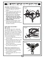
Fig. 33
COMPOUND CUT (FIG. 33)
A compound cut is the combination of a mitre and a bevel cut simultaneously.
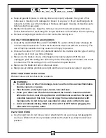
CUTTING BOWED MATERIAL (FIG. 34)
A bowed workpiece must be positioned
against the fence and secured with a
clamping devise before cutting. Do not
position workpiece incorrectly or try to cut
the workpiece without the support of the
fence. This will cause the blade to bind,
and could result in personal injury.
Fig. 34
WARNING:
The sliding fence must be extended to the left when making bevel cuts. The
sliding fence has been notched three bevel angles where the user must adjust
the fence to match the degree of the bevel cut. Failure to extend the sliding fence
will not allow enough space for the blade to pass through which could result in
serious injury. At extreme mitre or bevel angles the saw blade may also come in
contact with the fence.
!
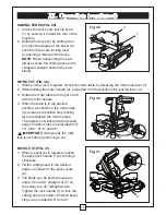
33.9° CROWN MOULDING (FIG. 32)
NOTE:
When cutting crown moulding the
bevel angle should be set 33.9
°
right or left.
1. Loosen the bevel lock handle (1),
2. Rotate the bevel stop block (2) and set
bevel angle at the 33.9° position.
3. Tilt the cutting arm to the left or right.
33.9
o
Fig. 32
1
2
3
1
2
Summary of Contents for Maximum Hawkeye Laser 055-6746-0
Page 46: ...46 Notes ...
Page 47: ...47 Notes ...
Page 48: ...48 Notes Imported by Mastercraft Canada Toronto Canada M4S 2B8 ...


