MasterCraft 062-3535-2 Instruction Manual Download Page 13

13

ASSEMBLY INSTRUCTIONS
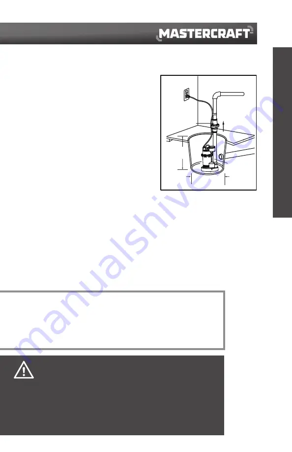
Minimum 

10" (25.4 cm) 

width

1/8" (3 mm)

anti-airlock 

hole

• Install the pump in sump pit with minimum diameter of 

10" (25.4 cm). The sump depth should be 14" (35.6 cm). 
Construct the sump pit of tile, concrete, steel or plastic. 
Check local codes for approved materials and for proper 
installation.

• Install the pump in a pit so that the switch operating 

mechanism has maximum possible clearance.

• The pump should not be installed on clay, earth or sand 

surfaces. Clean the sump pit of small stones and gravel 
which could clog the pump. Keep the pump inlet screen 
clear.

•  Install discharge plumbing. Use rigid plastic pipe and 

wrap threads with PTFE pipe thread sealant tape. Screw 
pipe into the pump hand tight plus 1 1/2 turns.

•  To reduce motor noise and vibrations, a short length of 

rubber hose 

[

1 7/8" (47.6 mm) I.D., e.g., radiator hose

]


can be connected into the discharge line near the pump using suitable clamps.

•  Install an in-line check valve or an in-pump check valve to prevent flow backwards through the pump 

when the pump shuts off.

• Power Supply: Pump is designed for 115 V, 60 Hz, operation and requires a minimum 15 A individual 

branch circuit. Plug the power plug into a 115 V GFCI power outlet.

•  If the pump discharge line is exposed to outside subfreezing atmosphere, a portion of the line 

exposed must be installed so any water remaining in the pipe will drain to the outfall by gravity. 
Failure to do this can cause water trapped in the discharge to freeze which could result in damage to 
the pump.

•  After the piping and check valve have been installed, the unit is ready for operation.
• Check the pump operation by filling the sump with water and observing pump operation through one 

complete cycle.

INSTALLATION

NOTE:

Do not use ordinary pipe joint compound on plastic pipe. Pipe joint compound can 
damage plastics.
If your check valve is not equipped with an air bleed hole to prevent an airlock in the 
pump, drill a 1/8" (3 mm) hole in the discharge pipe just above where the discharge 
pipe screws into the pump discharge. Be sure the hole is below the waterline and the 
check valve to prevent airlocks. 

•  Risk of flooding. Can cause personal injury and/or property damage. If a flexible discharge 
      hose is used, make sure the pump is secured in the sump to prevent movement. Failure 
      to secure the pump may allow pump movement, switch interference and prevent the pump 
      from starting or stopping.
•  Risk of flooding. Can cause personal injury and/or property damage. Failure to make an 
      operational check may lead to improper operation, premature failure, and flooding.

•  Risk of electric shock, fire or serious injury and/or death. Pump should always be electrically 
      grounded to a suitable electrical ground such as a grounded water pipe or a properly-grounded 
      metallic raceway, or ground wire system. Do not cut off the round ground pin.

CAUTION!

DANGER!

check valve

Minimum

14" (35.6 cm) 

depth

Summary of Contents for 062-3535-2

Page 1: ...IMPORTANT Please read this manual carefully before running this submersible sump pump and save it for reference INSTRUCTION MANUAL Submersible SUMP PUMP Model No 062 3535 2 ...

Page 2: ......

Page 3: ... contains important safety and operating instructions Read all instructions and follow them with use of this product TABLE OF CONTENTS 4 6 8 11 12 Quick Start Guide Technical Specifications Safety Guidelines Key Parts Diagram Assembly Preparation 13 14 15 16 17 Assembly Instructions Operating Instructions Maintenance Troubleshooting Warranty TABLE OF CONTENTS ...

Page 4: ...and check valve on the pump A Use non stick tape NOT pipe joint compound B Tighten the pipe into the pump C Install the check valve as close to the pump as possible D Drill an 1 8 3 mm anti airlock hole as shown The hole must be in the sump 2 INSERTING THE PUMP Place the pump in the sump making sure that nothing interferes with switch operation 3 1 1 4 3 2 cm or 1 1 2 3 8 cm Discharge Pipe Check V...

Page 5: ...over 5 PLUGGING IN THE PUMP Plug the pump into a 15 A circuit The circuit should be GFCI protected and dedicated to the sump pump Plastic pipe glue is extremely flammable Follow the glue manufacturer s instructions carefully if you are using glued plastic pipe for the discharge pipe Install in compliance with all applicable laws codes and ordinances Non compliance may cause product failure propert...

Page 6: ...nge 32 to 95 F 0 to 35 C Single phase Permanent split capacitor PSC Motor NEMA L torque curve oil filled squirrel cage induction class B insulation Seal Lip seal Discharge size 1 1 2 3 8 cm female national pipe thread FNPT or 1 1 4 3 2 cm FNPT with adaptor Cord length 10 3 m Cord size 18 AWG 3 1 P H 115 V AC Power 0 6 z H 0 5 4 3 M P R Full load amps 7 6 Cord type SJTW NOTE Do not reduce size of d...

Page 7: ...per hour 3600 13 627 3400 12 870 3000 11 356 2500 9 463 1900 7 192 1000 3 785 DIMENSIONS PERFORMANCE CHART 11 1 2 29 2 cm 7 3 4 19 7 cm 11 1 8 28 2 cm 9 1 4 23 5 cm ON OFF 6 3 4 17 2 cm 3 3 16 8 1 cm 4 10 2 cm 4 10 2 cm 9 11 16 24 6 cm 2 1 2 6 3 cm 3 1 2 8 9 cm Friction loss in piping not included in measurement ...

Page 8: ...as oil gasoline kerosene ethanol etc Do not use in the presence of flammable or explosive vapours Using this pump with or near flammable liquids can cause an explosion or fire resulting in property damage serious personal injury and or death Risk of electric shock Never remove the ground terminal on the three pronged power plug of the pump as the ground terminal is designed for protection Do not a...

Page 9: ...mel paint All surfaces should then be sprayed with a rust inhibiting oil Pump should be stored in its original shipping container On initial start up rotate impeller by hand to ensure seal and impeller rotate freely INSTALLATION DISCHARGE Discharge piping should be as short as possible A check valve is recommended for each pump being used The check valve is used to prevent backflow into the sump E...

Page 10: ...ut into service an insulation megger test should be performed on it The ohm values as well as the volts and amps should be recorded PUMP DOWN TEST After the pump has been properly wired and lowered into the basin sump or lift station it is advisable to check the system by filling with liquid and allowing the pump to operate through its pumping cycle The time needed to empty the system or pump down...

Page 11: ... KEY PARTS DIAGRAM PARTS LIST No Description Qty 3 Motor cap 1 No Description Qty 1 Power cord 1 4 Motor housing 1 2 Carry handle 1 5 1 1 4 3 2 cm adaptor 6 Pump outlet 7 Float switch 1 2 3 4 5 6 7 1 1 1 ...

Page 12: ...culates Not designed for use as a swimming pool drainer Flat head screwdriver Threaded adaptor pipe to pump 1 1 4 3 2 cm or 1 1 2 3 8 cm check valve 1 1 4 3 2 cm or 1 1 2 3 8 cm ABS or PVC pipe Hacksaw Cable ties Safety goggles Tape measure Cross head screwdriver Channel lock pliers Pipe wrench 12 ASSEMBLY PREPARATION ABS or PVC cement to match the pipe Thread tape 1 1 4 3 2 cm or 1 1 2 3 8 cm 90 ...

Page 13: ...maining in the pipe will drain to the outfall by gravity Failure to do this can cause water trapped in the discharge to freeze which could result in damage to the pump After the piping and check valve have been installed the unit is ready for operation Check the pump operation by filling the sump with water and observing pump operation through one complete cycle INSTALLATION NOTE Do not use ordina...

Page 14: ... damaged if allowed to run dry The motor is equipped with an automatic reset thermal protector If temperature in the motor should rise unduly the switch will cut off all power before damage can be done to the motor When the motor has cooled sufficiently the switch will reset automatically and restart the motor If the protector trips repeatedly the pump should be removed and checked Low voltage lon...

Page 15: ... pump Unscrew the stainless screws 5 and remove the volute 4 and gasket 3 Use a flat head screwdriver to hold the shaft 1 then turn the impeller 2 counter clockwise to release the impeller 2 Do Do Not When the power is disconnected inspect the pump suction screen and remove all debris then plug the pump back into the grounded GFCI outlet Do not disassemble the motor housing This motor has NO repai...

Page 16: ...o often The pump will not shut off The screen is blocked Debris is caught in the impeller or discharge The impeller is loose on the shaft or the impeller is broken There is a backflow of water from the piping or the check valve is leaking The float switch is stuck The switch is tangled The float switch is faulty The float is obstructed Reposition the pump and make sure the switch moves freely Repl...

Page 17: ... was sold to the original purchaser as a reconditioned or refurbished product unless otherwise specified in writing g this warranty will not apply to any product or part thereof if any part from another manufacturer is installed therein or any repairs or alterations have been made or attempted by unauthorized persons h this warranty will not apply to normal deterioration of the exterior finish such ...

Reviews: