MasterCraft 055-5511-4 Instruction Manual Download Page 12

12

FUNCTIONAL DESCRIPTION
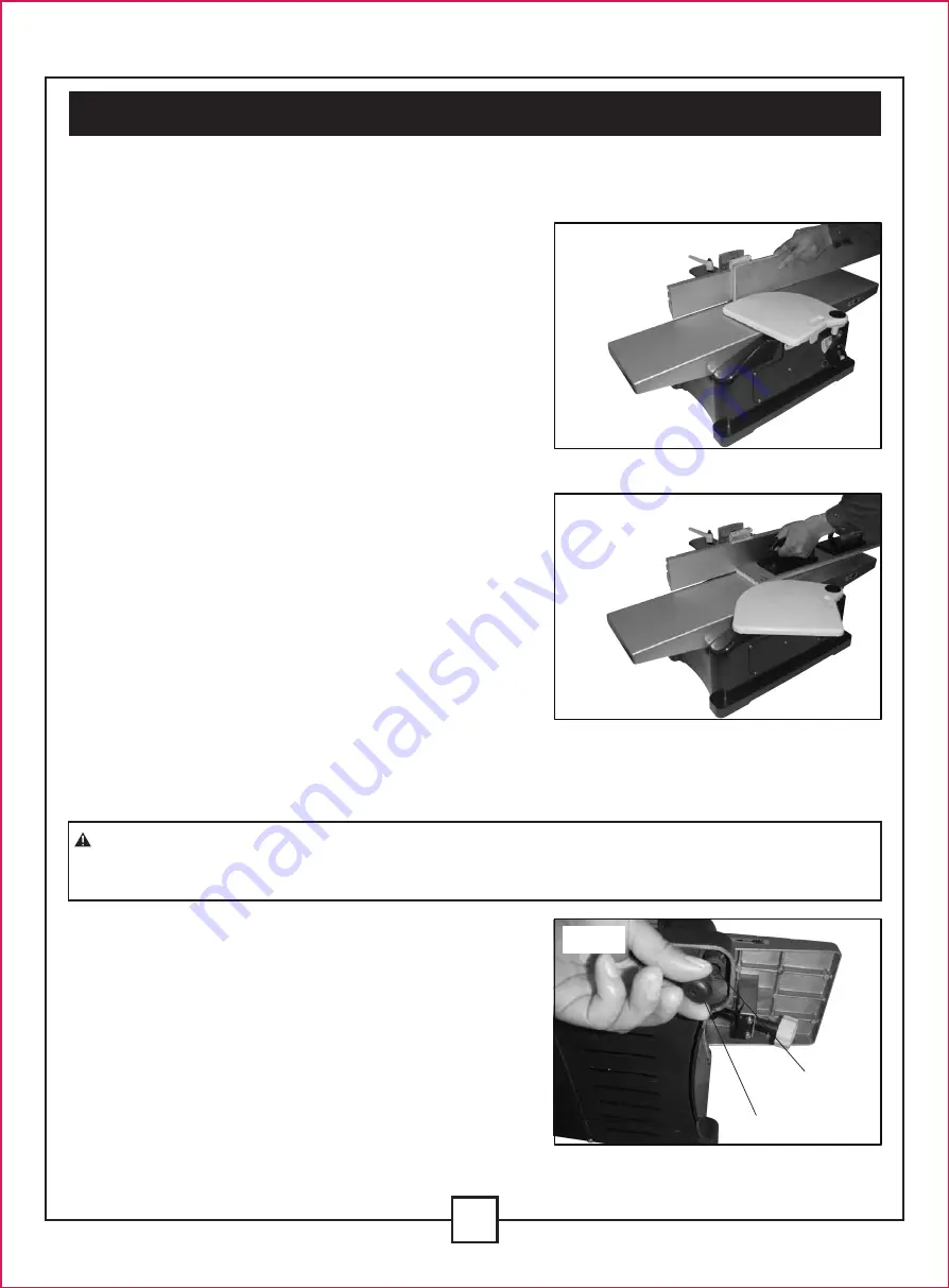
JOINTING OPERATION

Jointing cuts or edge jointing are made to square an

edge of a workpiece. The workpiece is positioned on

the jointer with the narrow edge of the workpiece on

the  infeed  table  and  the  major  flat  surface  of  the

workpiece against the fence, as shown in Fig. 1. The

workpiece is moved from the infeed table, across the

cutterhead to the outfeed table.

PLANING OPERATIONS

Planing  or  surfacing  is  identical  to  the  jointing

operation except for the position of the workpiece.

For planing, the major flat surface of the workpiece is

placed  on  the  infeed  table  of  the  jointer  with  the

narrow edge of the workpiece against the fence, as

shown in Fig. 2. The workpiece is moved from the

infeed table, across the cutterhead to the outfeed

table. Use  push  blocks  when  performing  planing

operations whenever possible.

V. Assembly and adjustments (continued)

Fig. 1

Fig. 2

INSTALLATION OF RUBBER FEET

- Insert the rubber feet (A) into the 4 holes (B) in the

base as shown Fig. 3.

ASSEMBLY

WARNING: 

For  your  own  safety, do  not  connect  the  machine  to  the  power  source  until

the machine is completely  assembled and you have read and understand the entire instruction

manual.

B

A

Fig. 3

Summary of Contents for 055-5511-4

Page 1: ...6 1 8 JOINTER Item No 055 5511 4 Instruction Manual Toll Free Helpline 1 800 689 9928...

Page 2: ...fety guidelines Electrical information Know your jointer Assembly and adjustments Operating instructions Maintenance Warranty Parts list Model Motor Speed Blade Max cutting depth Fence tilts In feed t...

Page 3: ...nd hearing protection can reduce your potential for injury But even the best guard won t make up for poor judgment carelessness or inattention Always use common sense and exercise caution in the works...

Page 4: ...elry which may get caught in moving parts Nonslip footwear is recommended Wear protective hair covering to contain long hair 12 ALWAYS USE SAFETY GLASSES Also use face or dust mask if cutting operatio...

Page 5: ...2 OBTAIN ADVICE from your supervisor instructor or another qualified person if you are not thoroughly familiar with the operation of this machine Knowledge is safety 3 FOLLOW ALL WIRING CODES and rec...

Page 6: ...RT LONG OR WIDE WORKPIECES Loss of control of the workpiece can cause injury 18 NEVER PERFORM LAYOUT ASSEMBLY OR SETUP WORK on the table work area when the machine is running A sudden slip could cause...

Page 7: ...cause serious injury Support the work piece adequately at all times during operation maintain control of the work at all times Do not back the work towards the infeed table Do not attempt to perform a...

Page 8: ...PROPERLY GROUNDED IF YOU ARE NOT SURE HAVE A QUALIFIED ELECTRICIAN CHECK THE RECEPTACLE 1 All grounded cord connected machines In the event of a malfunction or breakdown grounding provides a path of...

Page 9: ...An undersized cord will cause a drop in line voltage resulting in loss of power and overheating Fig B shows the correct gauge to use depending on the cord length If in doubt use the next heavier gaug...

Page 10: ...aning depth 5 In feed table 6 Planing depth adjustment knob 7 On Off switch 8 Clamping lever chamfering angle 9 Fence mounting bracket 10 Mounting hole 11 Fence sliding bracket 12 Clamping lever plani...

Page 11: ...mpare them against the list below Do not discard the carton or any packaging until the bench jointer is completely assembled Remove the protective coating from all unpainted surfaces This coating may...

Page 12: ...f the workpiece For planing the major flat surface of the workpiece is placed on the infeed table of the jointer with the narrow edge of the workpiece against the fence as shown in Fig 2 The workpiece...

Page 13: ...ten four hex nuts E at this time Position fence F Fig 6 so that rounded section G on bottom of fence is over cutterhead opening At the same time assemble the fence sliding bracket H and fence assembly...

Page 14: ...supporting surface Drill holes at each of the marked positions adjusting the diameter and depth of the holes to the socket head cap screws M8 x 45 mm used Place the bench jointer on the supporting su...

Page 15: ...nce positions of 90o and 45o to the left and right To check and adjust the positive stops proceed as follows Place a square C Fig 15 on the table with one end of the square against the fence as shown...

Page 16: ...n the direction shown Remove the holder D with the cutterhead from the cylinder in the direction shown Take the cutterhead E from the holder Place a new cutterhead onto the holder aligning the slots F...

Page 17: ...low the result will be as shown in Fig 25 and the finished surface will be curved If the cutterheads are set too high the work will be gouged at the end of the cut as shown in Fig 26 As a final check...

Page 18: ...position to prevent unauthorized use Grasp the switch toggle B and pull it out Fig 29 With the switch toggle B removed the switch will not operate However should the switch toggle be removed while the...

Page 19: ...ble as shown in Fig 31 The left hand should then be moved to the work on the outfeed table at the same time maintaining flat contact with the fence The right hand presses the work forward and before t...

Page 20: ...ning operations on material shorter than 10 25 4 cm narrower than 3 4 19 mm wider than 6 15 cm or less than 1 2 125 mm thick refer to Fig 35 NOTE Always use hold down push blocks for planing material...

Page 21: ...et together with an external vacuum cleaner takes care of the dust extraction of the working surface If necessary connect an adapter to the connection A Fig 38 Connect a vacuum cleaner to the machine...

Page 22: ...make sure the prongs on the cord plug are making good contact in the outlet Also check for blown fuses or open circuit breakers in the line LUBRICATION Apply household floor paste wax to the machine t...

Page 23: ...onsumable items such as but not limited to fuel lubricants vacuum bags blades belts sandpaper bits fluids tune ups or adjustments e This warranty will not apply where damage is caused by repairs made...

Page 24: ...rew Guide bar Guide bar base Nut Limit board B Wave washer Bolt Angle pointer Nut Bolt Guide bar angle base Screw Bolt Washer Stand B Big washer Locking screw groupware Bolt Stand T Nut Active worktab...

Page 25: ...2 Guard cover Guard Pin Ring Spring Buffer block Bolt Open ring Arm Fixed base Bolt Bolt Nut Carbon brush Brush 1 1 1 1 2 1 1 1 1 1 1 4 2 2 1 Description Qty Motor housing Inductance Ball bearing Sta...

Page 26: ...27 25 24 23 22 17 14 13 12 7 7 7 6 5 4 8 2 1 1 3 9 7 12 15 16 10 10 11 18 19 19 20 20 21 21 25 19 26 26 28 33 32 32 31 31 29 30 36 59 59 55 55 55 58 36 36 37 37 60 59 59 59 59 59 59 59 59 59 65 63 64...

Reviews: