Masoneilan 39003 Series Instruction Manual Download Page 13

11

11

Instructions EM39003 - 05/10
39003 Series High Performance butterfly Valves

ANSI Class 600 3" – 14"

Lug Valves

Wafer 

Valves

Bolt Engagement in Valve*

Studs & Nuts

Machine Bolts

Studs & Nuts

Valve

Size

Valve

Series

Thread

Size

Qty

  A

Length

A

Qty

B

Length

B

Qty

C

Length

C

Qty

D

Length

D

Qty

F

Length

F

Qty

G

Length

G

Qty

E

Length

E

3"

g

¾-10

8

1.034

8

1.026

8

3.50

8

3.50

8

2.25

8

2.38

8

7.00

4"

g

7

/

8

-9

8

1.274

8

1.165

8

3.50

8

3.25

8

2.75

8

2.75

8

7.75

6"

g

1-8

12

1.274

12

1.306

12

4.75

12

4.75

12

3.25

12

3.25

12

9.50

8"

g

1

1

/

8

-8

12

1.794

12

1.795

12

5.75

12

5.75

12

4.12

12

4.12

12

11.50

10"

H

1¼-8

12

2.495

12

2.000

12

6.75

12

6.25

12

5.00

12

4.50

12

13.00

H

1¼-8   4**

1.375

4**

2.000

4**

5.50

4**

6.25

4**

3.88

4**

4.50

8**

6.25

12"

H

1¼-8

16

2.683

16

2.697

16

7.00

16

7.00

16

5.38

16

5.38

16

14.00

H

1¼-8

4**

1.325

4**

1.765

4**

5.25

4**

6.00

4**

4.00

4**

4.38

8**

6.00

14"

H

1

3

/

8

-8

16

2.994

16

2.996

16

7.50

16

7.50

16

CF

16

CF

16

15.00

H

1

3

/

8

-8

4**

1.506

4**

1.869

4**

6.00

4**

6.50

4**

CF

4**

CF

8**

6.50

Maintenance Instructions

3.1  Safety Precautions

before removing the valve from the line or loosening any bolts, 
it is important to verify the following conditions:

1. 

be sure the line is depressurized and drained.

2. 

be sure of the pipeline media. Proper care should be taken 
for protection against toxic and/or flammable fluids.

3. 

never  install  the  valve  without  an  Operator  (Manual  or 
Automatic) already attached to the valve shaft.

4. 

never remove the Operator from the valve while the valve is in 
the pipeline under pressure. The eccentric valve design may 
allow line pressure to open the valve if the handle/actuator is 
not in place while the valve is under pressure.

5. 

Always  be  sure  that  the  disc  is  in  the  full  closed  position 
before removing or installing the valve.

6. 

Take care in handling the valve. Personal injury or property 
damage may result if the valve is damaged or mishandled 
during maintenance operations.

3.2  General Maintenance

normal  maintenance  for  a  Masoneilan  HPbV  is  limited  to 
adjustment  of  the  shaft  packing  by  tightening  down  evenly 
on  the  gland  flange  using  the  gland  flange  studs  and  nuts. 
Overtightening  of  the  gland  should  be  avoided  since  this  will 
shorten  the  life  of  the  packing.  During  commissioning,  it  is 
common  for  dirt  and  foreign  objects  to  be  left  in  the  pipeline 
during construction. This debris can damage the HPbV seat or 
disc edge which will prevent the valve from providing tight shut-
off. In such cases seat replacement may be necessary. 

3.3  Packing Replacement

1. 

Remove the handle or actuator and the mounting hardware 
from the valve.

2. 

Remove the gland flange nuts and lockwashers.

3. 

Remove the gland flange and gland.

4. 

Replace  the  old  packing  with  new  packing.  Correct 
packing selection is important. On larger valves it may be 
necessary to compress each stem seal into the stuffing box 
before adding the next one.

5. 

Reinstall gland, gland flange, lockwashers and nuts.

6. 

Tighten the gland flange nuts evenly to torque specified in 
Table 1.

7. 

Operate the disc several times.

8. 

Reinstall the handle or actuator and mounting hardware.

9. 

Set the actuator stops.
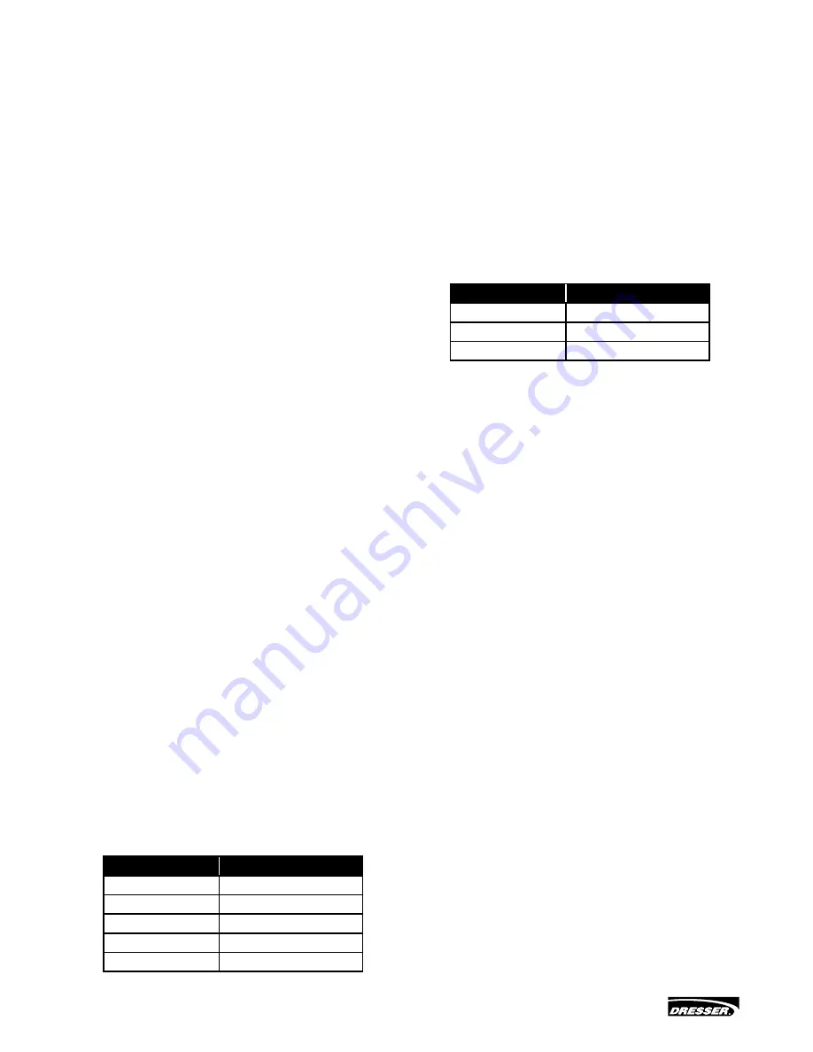
Table 1

Valve Size (in.)

Torque (in.-lb.)

2 to 8

25

10 to 12

35

14 to 20

50

24 to 30

75

36 to 48

100

3.4  End Cap Seal Replacement

(where applicable)

1. 

Remove the end cap bolts and lockwashers.

2. 

Rotate the end cap to break the seal, then pull the cap out.

3. 

Remove the old seal.

4. 

Clean the body and end cap prior to installing the new seal.

5. 

Slide the new seal into place, then guide the end cap into 
the body.

6. 

Align the bolt holes and reinstall the lockwashers and bolts.

7. 

Tighten the bolts evenly to the torque specified in Table 2.

Table 2

Valve Size (in.)

Torque (in.-lb.)

2 to 8

50

10 to 12

80

14 to 30

100

3.5  Standard Soft Seat Replacement

1. 

Place the valve on a bench with the seat retainer facing up. 
Use blocks to elevate the valve above the work surface to 
provide enough clearance to prevent the disc from being 
damaged when the valve is opened.

2.   A.  Cap Screw Retainer:


 Remove the cap screws and lift the seat retainer out of 
the valve.


B.  Wedge Ring Retainer:


 Unlock  the  retainer  by  removing  the  set  screws.  If 
difficulty is experienced in removing the retainer, open 
the  disc  approximately  20  degrees  and  then  tap  the 
retainer  with  a  non  metallic  hammer.  Lift  the  retainer 
from the body.

3. 

Remove the old seat from the seat retainer and discard.

4. 

Thoroughly clean the seat cavity in the body and the seat 
retainer prior to installing a new seat.

5. 

Carefully  clean  and  polish  the  disc  sealing  surface  with  a 
soft  cloth.  The  disc  sealing  surface  should  be  free  of  all 
grooves and scratches.

6. 

Place  the  seat  retainer  on  a  flat  surface  with  the  seat 
locating area facing up.

7. 

Place the new preformed seat assembly (Seat and O-ring) 
on  the  seat  retainer  with  the  marked  (tape)  side  facing 
down.

8. 

Using  the  balls  of  each  thumb,  press  down  on  the  seat 
engaging  the  shoulder  of  the  seat  behind  the  lip  in  the 
seat  retainer.  Stretch  the  seat  into  place  by  sliding  each 
thumb  around  the  circumference  of  the  seat  maintaining 
downward pressure and forcing the seat shoulder over the 
seat retainer lip.

Summary of Contents for 39003 Series

Page 1: ...Instruction Manual EM39003 05 10 39003 Series High Performance Butterfly Valves Putting You In Control ...

Page 2: ...9 Offset Disc Design 5 1 10 Seat Retainer Alternatives 6 2 Installation Recommendations 2 1 Valve Ratings 6 2 2 Seat Upstream vs Seat Downstream 6 2 3 Disc Clearances 7 2 4 Opening Rotation 7 2 5 Installation Position 7 2 6 Valve and Flange Preparation 7 2 7 Installation Tools 7 2 8 Required Bolting 7 2 9 Unpacking and Storage Instructions 7 2 10 Pre Installation Procedure 7 2 11 Valve Installatio...

Page 3: ...hange without prior notice The information contained in this manual in whole or part shall not be transcribed or copied without Masoneilan s written permission Please report any errors or questions about the information in this manual to your local supplier These instructions are written specifically for the 39003 Series High Performance Butterfly Valves and do not apply for other valves outside o...

Page 4: ...ated beyond the seat The 39003 Series valve is bi directional but the preferred installation position is with the seat in the upstream position SUS Note the arrow on the metal tag attached to the valve body for preferred direction of flow 1 3 Flange Compatibility The 39003 Series valve is designed to fit between flanges as follows ANSI Class 150 2 through 24 MSS SP 44 Class 150 30 through 48 ANSI ...

Page 5: ... 1 ATC FTO ATO FTO ATO FTO Actuator Mounting 0 Undefined 1 Horizontal above center Valve opens on stem extension air to open action 2 Horizontal above center Valve closes on stem extension air to close action 3 Vertical above center Valve opens on stem extension air to open action 4 Vertical above center Valve closes on stem extension air to close action 5 Horizontal below center Valve opens on st...

Page 6: ...urn piston actuator Actuator Type Design Series 3 Actuator Mounting 0 Undefined 1 Parallel to pipe Air to open action 2 Parallel to pipe Air to close action 3 Perpendicular to pipe Air to open action 4 Perpendicular to pipe Air to close action 5 Parallel to pipe Air to open action 6 Parallel to pipe Air to close action 7 Perpendicular to pipe Air to open action 8 Perpendicular to pipe Air to close...

Page 7: ...etal and soft seats with the metal seat being designed to function during and after a fire Valves of this type are referred to as Fire Safe and are tested to meet API 607 Fire Safe specifications and operation criteria Metal Seats are well suited for higher temperature applications and provide shut off to ANSI B16 104 Class IV 1 9 Offset Disc Design All Masoneilan HPBVs have both off set discs and...

Page 8: ...nge mating surface Two types of seat retainer fastening designs are used in Masoneilan HPBVs Installation Recommendations 2 1 Valve Ratings Masoneilan HPBVs are intended for use at the pressure and temperatures indicated on the metal nameplate attached to each individual valve Check the valve operating temperature and pressure ratings on the valve nameplate before proceeding with installation 2 2 ...

Page 9: ...luded with the valve shipment 2 9 Unpacking and Storage Instructions 1 Check the packing list against the valve received to verify that the size material and trim are correct 2 Check to make sure that the valve and operator were not damaged during shipment 3 When lifting the valve take care to avoid damage to the flange faces disc sealing edge or operator On larger valves lifting holes are provide...

Page 10: ... length or the valve is equipped with volume boosters 3 8 tubing is preferred All connections must be free of leaks Do not exceed loading pressure indicated on a warning tag located on the upper diaphragm case 2 Changing Actuator Position For each valve action air to open or air to close the actuator and bracket may be mounted in any one of four recommended positions see Figure 1 Actuator position...

Page 11: ... G 11 8 8 16 5 75 16 4 75 16 4 38 16 3 25 16 11 00 20 G 11 8 8 16 6 75 16 4 75 16 5 12 16 3 25 16 11 50 G 11 8 8 4 5 50 4 4 75 4 4 12 4 3 25 4 5 50 24 G 11 8 8 20 7 25 20 5 75 20 5 63 20 4 25 20 13 00 30 H 1 8 24 7 75 24 7 75 24 6 25 24 6 25 24 16 00 H 1 8 4 6 50 4 6 25 4 5 00 4 4 63 4 6 50 36 H 1 8 28 9 50 28 9 50 28 7 75 28 7 75 28 19 50 H 1 8 4 7 50 4 7 25 4 5 75 4 5 50 4 7 50 42 H 1 8 32 10 00...

Page 12: ...8 4 1 681 4 1 750 4 5 75 4 5 50 4 4 19 4 4 00 8 5 75 24 H 1 8 20 3 560 20 3 510 20 8 25 20 8 25 20 6 31 20 6 25 20 16 50 H 1 8 4 1 800 4 1 750 4 6 25 4 6 25 4 4 56 4 4 50 8 6 25 30 H 1 8 24 4 331 24 4 429 24 10 25 24 10 50 24 7 88 24 7 88 24 20 50 H 1 8 4 2 039 4 2 071 4 8 00 4 8 00 4 5 44 4 5 47 8 8 00 ANSI Class 600 3 14 Lug Valves Wafer Valves Bolt Engagement in Valve Studs Nuts Machine Bolts S...

Page 13: ...rs and nuts 6 Tighten the gland flange nuts evenly to torque specified in Table 1 7 Operate the disc several times 8 Reinstall the handle or actuator and mounting hardware 9 Set the actuator stops Table 1 Valve Size in Torque in lb 2 to 8 25 10 to 12 35 14 to 20 50 24 to 30 75 36 to 48 100 3 4 End Cap Seal Replacement where applicable 1 Remove the end cap bolts and lockwashers 2 Rotate the end cap...

Page 14: ...2 to 12 50 14 to 20 75 24 to 48 100 3 6 Fire Safe and Metal Seat Replacement 1 Follow Steps 1 and 2 of Soft Seat Replacement instructions 2 Remove old soft seat and graphite gaskets and discard Clean and inspect the metal seat 3 If metal seat is scored bent or otherwise damaged it will require replacement 4 Thoroughly clean the seat cavity in the body and the seat retainer prior to installing the ...

Page 15: ...The bearings should be installed into the shaft bore firmly against the counterbore or bottom of shaft hole A Valves 2 thru 12 With the valve body on edge on the bench shaft horizontal and the body overtravel stop nearest to the bench position the disc in the open position with the flat face upward Present the disc to the valve body from the side opposite the seat retainer cavity B Valves 14 and l...

Page 16: ... Follower 11 End Cap 12 End Cap Bolts 13 Set Screws 14 Wedge Pins 15 Gland Flange Stud 16 Gland Flange Nut 17 Lockwasher 18 Wedge Ring 19 End Cap Seal Through Shaft Design Item Description 1 Body 2 Seat Retainer 3 Disc 4 Shaft 5 Seat 6 Seat O ring 7 Bearing 8 Packing 9 Gland 10 Gland Follower 11 Disc Thrust Spacer 2 5 12 Set Screws 13 Wedge Pins 14 Gland Flange Stud 15 Gland Flange Nut 16 Lockwash...

Page 17: ...ng the actuator to the mounting bracket 3 Lift the actuator off the mounting bracket Rotate the actuator 180 4 Align the drive coupling with the actuator shaft and install the actuator on the mounting bracket 5 Reinstall the bolts and lockwashers to fasten the actuator to the mounting bracket Tighten to torque specified in Table 4 6 Adjust the actuator stops as described previously 3 10 Remote Act...

Page 18: ...pring exerting force to open the valve In such a case while disassembling the disc could suddenly snap open possibly causing injury When the actuator stem is fully extended the spring is exerting force in the opposite direction If the disc is jammed closed on an air to close unit use external air pressure to hold the actuator in a closed position and complete the necessary steps in this section to...

Page 19: ...ion bolts 72 The tension nuts 73 attached to the tension bolts 72 must be removed evenly and must also be the last items disassembled The following procedure must be followed to avoid injury 1 Isolate the valve vent process pressure and shut off all electrical signal air and supply lines to the valve 2 If equipped with a handwheel it must be rotated to the disengaged position 3 Remove air supply p...

Page 20: ...n the same orientation as the first lever F Slide indicator item 2 as indicated in Figure 15 loosely over top of shaft do not tighten clamp screw at this time Then continue to slide shaft into yoke until step on shaft 77 contacts ball bearing 9 as indicated in Figure 15 G Install woodruff key 80 in shaft 77 Align key 80 in shaft 77 with keyway in coupling then slide coupling onto shaft 77 H Instal...

Page 21: ...ther side of the bearing D Install locknut 51 and finger tighten only E Install retaining ring 28 7 Handwheel to Bracket Assembly The handwheel is always installed on the same side of the bracket as the actuator To install the handwheel assembly proceed as follows A Insert handwheel shaft 22 through appropriate bracket hole and onto lever arm 18 and install clevis pin 20 and retaining clips 21 B I...

Page 22: ...Lever Arm Pin 18 Lever Arm 19 Lever Arm Bearing 20 Clevis Pin 21 Retaining Clips 22 H W Shaft S A 23 Handwheel Bracket 24 Cap Screw 25 Lock Washer 26 Pivot Pin 27 Handwheel Pivot 28 Retaining Ring 29 Thrust Washer H W 30 Needle Bearing 31 Bearing Race 32 O Ring 33 End Cap 34 Handwheel Plate 35 H W Plate Screw 36 Handwheel 37 Indicator Dot 38 Side Cover 39 Serial Plate 40 Drive Screw 41 Bottom Cove...

Page 23: ...Instructions EM39003 05 10 39003 Series High Performance Butterfly Valves 21 Section B B Figure 14 Figure 15 Figure 16 View C C Figure 17 Section A A ...

Page 24: ...Instructions EM39003 05 10 39003 Series High Performance Butterfly Valves 22 Figure 19 Figure 20 Figure 18 Figure 21 ...

Page 25: ...Instructions EM39003 05 10 39003 Series High Performance Butterfly Valves 23 Notes ...

Page 26: ...Instructions EM39003 05 10 39003 Series High Performance Butterfly Valves 24 Notes ...

Page 27: ...Instructions EM39003 05 10 39003 Series High Performance Butterfly Valves 25 Notes ...

Page 28: ...n Green Phone 44 1628 536300 Fax 44 1628 536319 UNITED STATES Massachusetts Phone 1 508 586 4600 Fax 1 508 427 8971 Corpus Christi Texas Phone 1 361 881 8182 Fax 1 361 881 8246 Dresser Direct Deer Park Texas Phone 1 281 884 1000 Fax 1 281 884 1010 Dresser Flow Technologies Houston Texas Phone 1 281 671 1640 Fax 1 281 671 1735 California Phone 1 562 941 7610 Fax 1 562 941 7810 DIRECT SALES OFFICE L...

Reviews: