


Instructions EM39003 - 05/10
39003 Series High Performance butterfly Valves
8
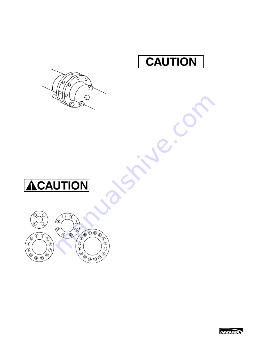
1. For Wafer Style Valves:
A.
Loosely install the lower flange bolts to form a cradle
between the flanges. (See Figure 9.)
B.
noting the flow direction arrow on the tag, place the valve
and flange gaskets between the flanges, making sure the
arrow on the tag points in the direction of the flow.
C.
Install the remaining flange bolts, shifting the valves as
necessary to permit the bolts to pass by or through the
valve body.
Figure 9
For Lug Style Valves:
A.
noting the flow direction arrow on the tag, place the valve
between the flanges, making sure the arrow on the tag
points in the direction of the flow.
B.
Install the lower flange bolts loosely, leaving space for the
flange gaskets.
C.
After inserting the flange gaskets, install the remaining
bolts.
2.
Using the sequence shown in Figure 10 tighten the flange
bolts evenly to assure uniform gasket compression.
The valve should be centered between the flanges and gaskets
to prevent damage to the disc edge and shaft as a result of the
disc striking the flange, gasket, or pipe.
Figure 10
3.
If an actuator is to be used, air hoses or electricity should
be connected to the unit as specified.
4.
The valve is now ready for operation.
Remember: Install the valve with the disc in the FULL
CLOSED POSITION.
2.12 Actuator Installation
1. Actuator Air Piping
The Model 33 actuator used with the High Performance butterfly
Valve is designed to accept 1/4" nPT air supply piping. Use 1/4"
OD tubing or equivalent for all air lines. If the air line exceeds
25 ft. in length, or the valve is equipped with volume boosters,
3/8" tubing is preferred. All connections must be free of leaks.
Do not exceed loading pressure indicated on a warning tag
located on the upper diaphragm case.
2. Changing Actuator Position
For each valve action, air to open or air to close, the actuator
and bracket may be mounted in any one of four recommended
positions (see Figure 1). Actuator position is usually determined
by adjacent piping, obstacles of various types or piping
arrangements. Valves may be rotated 180° around the axis
of the shaft, if necessary. In such a case, no disassembly is
required, other than repositioning gauges so they are not upside
down. (However, note caution in Figure 1). note also that the
preferred flow direction is reversed. If it becomes necessary to
rotate the actuator position 90°, partial disassembly is required.
Depending on whether the valve is or is not equipped with a
handwheel, select the appropriate section in this instruction and
proceed.
3. Changing Actuator Action
For the positions shown in Figure 1, the valve action is air to
open or air to close. In both cases the actuator stem extends
with admission of air to the actuator. Changing valve action
requires partial disassembly in repositioning the actuator to the
other hole in the bracket and reorientation of linkage. Refer to
Figures 19 and 20. If the valve is equipped with a handwheel, it
must be repositioned to the opposite side of the bracket.
Note: The handwheel is always installed so it operates
against the actuator spring force. The handwheel is
always located on the same side of the bracket as the
actuator (see Figures 19 and 20). Depending on whether
the valve is or is not equipped with a handwheel, select
the appropriate section on disassembly and proceed.


