Instructions
EY0171-0172
10/08
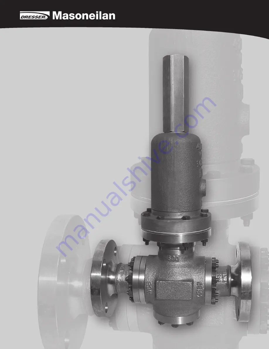
171 and 172 Series
Self-OperatingPressure Regulators
DV-215-171_172 series Inst-v13.indd 3
11/5/08 12:13:35 PM
Page 1: ...Instructions EY0171 0172 10 08 171 and 172 Series Self Operating Pressure Regulators ...
Page 2: ...ION 7 4 3 INSTALLATION 8 4 4 INSTALLATION DIAGRAMS 8 4 5 START UP AND CALIBRATION 8 4 6 MAINTENANCE 8 Caution The instructions on the following pages should be thoroughly reviewed and understood prior to installing operating or performing maintenance on this equipment Throughout the text safety and or caution notes will appear and must be strictly adhered to otherwise serious injury or equipment m...
Page 3: ...cates important facts and conditions About this Manual The information in this manual is subject to change without prior notice The information contained in this manual in whole or part shall not be transcribed or copied without Masoneilan s written permission Please report any errors orquestions about the information in this manual to your local supplier These instructions are written specificall...
Page 4: ...ring Packs can be placed on pallets if required Follow all and any indications written on the packaging Operators moving loads must take all necessary precautions to prevent accidents Storage Regulators must be kept in a dry place to protect them from atmospheric conditions They may only be removed from their crates or packing immediately prior to installation The end protections and covers must b...
Page 5: ...ames and versions Part 1 Blindhead 2 Gasket Set 3 Body 4 H P Insert 5 Inlet Flange 6 Plug 7 Diaphragm Case 8 Diaphragm 9 Protector optional 10 O Ring 11 Diaphragm Plate 12 Spring 13 Spring Case 14 Lock Nut 15 Adjusting Screw 16 Spring Button 17 Nut 18 Spring Guide 19 Screw 20 Nut 21 Diaphragm Plate Lower 22 Screw 23 Guide 24 Outlet Flange 25 Disc 26 Stud 27 Nut 28 Plug Screw 29 Screw 30 Cap 31 Bal...
Page 6: ...nstructions EY0171 0172 10 08 171 and 172 Series Self Operating Pressure Regulators This pipe shall be linked to ATEX form Gr II Cat 2 only in case of non high explosive atmosphere Fig 8 Pressure reduction system 1 Reducing regulator 2 safety relief valve 3 pressure gauge 3 2 4 Please keep in mind that the regulated pressure sens ing port is located inside the regulator therefore the pressure drop...
Page 7: ...m bracket assembly is fully rotated to the right and left each hole rotates by the same angle as the matching hole on the actuator flange This means that the bracket is at right angles to the high pressure insert Match the holes of the diaphragm with the holes in the actuator flange and install the spring spring button and spring case Install the blindhead 1 Return the Instructions EY0171 0172 10 ...
Page 8: ...phragm Plate 7 Diaphragm 8 O Ring 9 Spring Case 10 Spring 11 Nut 12 Screw 13 Gasket 14 Lock Nut 15 Packing Gland 16 Bearing 17 Spring Button 18 Adjusting Screw 19 Spring Guide 20 Screw 21 Nut 22 Screw 23 Plug 24 H P Insert 25 Outlet Flange 26 Stud 27 Nut 28 Plug Screw 29 Disc 30 Inlet Flange 31 Pin 32 Screw Recommended spare parts Note Parts 7 and 8 are supplied in one set only Note Actuator sizes...
Page 9: ...Spring 11 Nut 12 Screw 13 Gasket 14 Lock Nut 15 Packing Gland 16 Bearing 17 Spring Button 18 Adjusting Screw 19 Spring Guide 20 Screw 21 Nut 22 Screw 23 Plug 24 H P Insert 25 Outlet Flange 26 Stud 27 Nut 28 Plug Screw 29 Disc 30 Inlet Flange 31 Pin 32 Screw 33 Nut 34 Actuator Ring 35 Intermediate Plate Recommended spare parts Note Parts 7 and 8 are supplied in one set only Note Actuator sizes 220 ...
Page 10: ...tors 172 50 Double Diaphragm Versions The 172 50 regulators comprise two groups of regulators Group 1 All the group 1 regulators have just one diaphragm one of the controlled pressures acts under the diaphragm through an internal sensing line connection while the other acts over the diaphragm through a sensing line connection on the spring housing The plug is kept open by the spring The following ...
Page 11: ...O rings 8 should not be re used 4 6 6 Reassembly Carry out the dismounting operations in reverse order Push the stem of the plug into the guide and put the high pressure insert into position with the pin 31 For regulators with flanged ends put the flange into position tighten the nuts or screws uniformly Install the Diaphragm s see 4 6 3 taking care to properly arrange the Teflon protectors if equ...
Page 12: ...Texas Phone 832 590 2303 Fax 832 590 2529 California Phone 562 941 7610 Fax 562 941 7810 DIRECT SALES OFFICE LOCATIONS Aftermarket Value Services Dresser Masoneilan a leading manufacturer of automated process control solutions offers world class global aftermarket services Consistent and high quality services executed through a network of fully authorized and certified third party service centers ...