VFlo Control Valves
3
PREVENTIVE MAINTENANCE
Twice yearly, operation should be checked for trouble free
performance. For the preventive maintenance, follow the steps
that are presented below:
These steps can be very well performed while the valve is in line
and, in some cases, without interrupting service. Refer to the
"Disassembly" and "Reassembly" section if an internal problem is
suspected with the valve.
Tighten flange bolting if signs of gasket leakage through the
body and line flanges are observed (See Table I for
specifications.)
Observe whether any corrosive fumes or process drippings
are damaging the valve.
Valve should be cleaned and areas of severe oxidation
painted.
Packing nuts should be tightened as necessary to prevent
Gland leakage.
CAUTION :
Over tightening of packing can cause
excessive packing wear and high shaft friction, which may
retard shaft rotation.
Where the valve is supplied with a lubricator, lubricant supply
and level needs attention. Ensure proper supply and level of
the lubricant.
Where possible, stroke valve and observe for smooth, full-
stroke operation by looking at the position indicator plate
mounted on the transfer case. An internal valve problem is
indicated by unsteady movement of the plate.
In case of a positioner being present, its calibration needs to
be checked by observing the actuator position indicator plate
and gauges. The positioner needs calibration to the correct
range.
In case an actuator is attached, the appropriate maintenance
instructions for preventive maintenance need to be referred.
Where possible, remove the air supply to observe the
actuator stroke plate for correct fail-safe action.
Ensure fastening of all valve accessories, brackets and
bolting.
The exposed portion of the valve shaft must be free from dirt
or foreign material.
I case an air filter is present, the cartridge needs to be
checked and if necessary, replacement needs to be done.
Removing Valve From Line
To remove the valve from the line, in cases where an internal
problem is suspected proceed as mentioned below:
WARNING :
Line must be depressurized to atmospheric pres-sure.
All process fluids should be drained. If caustic or hazardous materials
are present, decontaminate the valve. This is very important as it will
prevent any possible injury.
1.
2.
3.
4.
5.
6.
7.
8.
9.
10.
11.
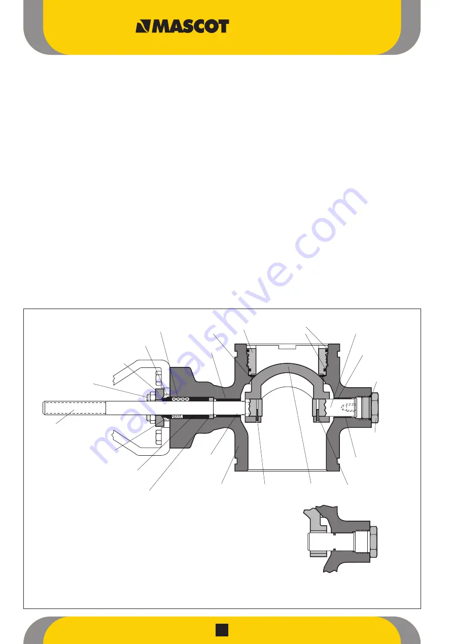
Figure 1: 3", 12" and 16" VFlo Body Assembly with Rotating Post Design
Note : Item numbers correspond to bill of material of Valve. Please refer to it for specific part numbers.
Stationary Post Design
Packing
(Item No. 88)
Packing Stud
(Item No. 109)
Gland Flange
(Item No. 80)
Packing Nut
(Item No. 117)
Shaft
(Item No. 51)
Retainer
Retainer O-rings
(Item No. 30)
(Item No. 59)
(Item No. 56)
Seals*
Shaft Bearing
(Item No. 83)
Post Bearing
(Item No. 84)
Shaft O-ring
(Item No. 62)
(optional)
O-ring
(Item No. 61)
Post
(Item No. 123)
Post O-ring
(Item No. 64)
(optional)
Plug
(Item No. 122)
Body
Shaft Pin
Ball
(Item No. 1)
(Item No. 52)
(Item No. 50)
Post Pin
(Item No. 121)
Packing Follower
(Item No. 87)
Packing Spacer
(Item No. 93)
Thrust Bearing
(Item No. 53)
(*See Figure 4 for seal configurations and item numbers.)


