


Mas Grup
5
6. ASSEMBLY / INSTALLATION
In our standard production, the pump and the motor have been installed
vertically in a common base plate.
6.1. Location of Installation
Pump shall be installed in a location where the control and the
maintenance of the pump are easily made. The pump room shall be
suitable for operation of lifting systems such as freight elevator, forklift,
etc.
The pump group should be installed in the lowest possible location of the
pumping system in order to achieve the highest suction pressure.
6.1.1. Location of Installation- Local Ambient Temperature
When the local ambient room temperature exceeds +40
o
C in a pumping
system, suitable ventilation should be provided in order to remove the
heat dissipated to the environment and supply fresh air.
6.2. Type of Connection
Type of connection depends on the design type and the size of the pump
and the motor, as well as the local installation conditions. Foot-mounted
vertical pump-motor units have been installed in a common base plate.
6.3. Piping
6.3.1. General
Do not use the pump as the hinged support for the piping system.
Put enough supports under the piping system in order to carry the
weight of the pipe and fittings.
Avoid piping system loads on pump by installing flexible components
(compensator) to suction and discharge of the pump.
By mounting flexible supporting items, take into consideration the fact
that these items may elongate under the pressure.
Suction pipe shall be in a constantly increasing slope to the pump. Air in
the suction pipe shall be arranged to move into the pump
Discharge piping shall be in a constantly increasing slope to the
reservoir or discharge point, without up and downs which can cause air
pockets in the piping system. At locations where forming of air pockets
is possible, special items like air valve and air cock are mounted to
evacuate the trapped air.
It is important that pipe diameter and fittings are at least as much as the
pump opening diameter or preferable one or two size higher. One
should never use fittings with smaller diameters than the pump exit
diameter. In particular, preferred fittings like foot valve, strainer, filter,
check valves and valves shall have large free passing area, and low
friction loss coefficient.
For piping systems with hot liquids, thermal expansions are to be taken
into account and compensators shall be mounted in accordance with
these expansions. Caution shall be exercised to avoid the loading of
pump in this installation.
6.3.2. Specification of Work in Piping Installation
In installation of pipes, follow the procedures below certainly.
•
Take out the guards (placed by the manufacturer) from suction and
discharge openings of the pump.
•
Close the suction and discharge flanges with rubber gaskets. This
precaution is important to avoid the undesired substances (weld crust,
weld slag, sand, stone, wood piece etc.) get into the pump. Do not take
off this gasket until the installation is completed.
•
Start the installation of piping from the pump side. Do the necessary
assembling and welding of the parts in a successive order.
•
In these operations, do not neglect to put the necessary supports in
their respected locations.
•
Following above procedure, complete all piping system at suction side
up to the suction tank (or foot valve if available), at discharge side up to
do discharge collector and discharge pipe.
•
When all installation and welding process is done and the heat
dissipated by welding is removed, dismantle all the bolted connections
from the suction tank to discharge pipe. Take out all demountable parts.
•
Clean these parts and then paint body coat completely inside and
outside.
•
Mount the parts again in their intended places. However, this time start
from the discharge line and move downward to the pump. In this
instance, do not forget to check the flange gaskets. If needed, (for
example deformation during welding) replace them.
•
Concerning the connection of the pump flanges to piping, in case of
misalignment of axis and flange holes, do not force the system to
eliminate the misalignment. Forcing the system may cause difficult-to-
correct problems.
•
If there is an axial misalignment between the flanges of the pump and
the pipe, due to the welding or any other reasons, cut the pipe from a
suitable location in order to fix the problem. Connect the pipe (pump
side) to the pump. After carrying out the necessary correction, connect
the parts again by welding.
•
Dismantle and clean the last welded part. Repaint again and mount on
its place.
•
After all these processes are accomplished, remove the rubber gasket
from the suction and discharge openings. Open their holes and mount
them again on their intended place.
6.3.3. Specification of Work after Installation of Piping and Piping
System
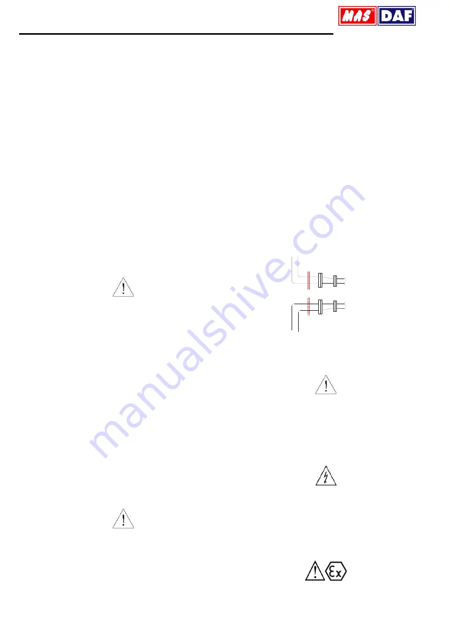
Installing Pipes
Suction line (top wiew)
Suction line (bottom wiew)
Suction flange
Suction flange
Figure 3:
Piping System
An illustrative piping system is shown in Figure 6. Appropriate
manometers shall be mounted on suction and discharge pipe lines.
Complete the auxiliary pipe connections in piping system if exist (cooling
to bearing housing, and stuffing box (seal), relief pipe, oil pipe etc.)
6.4. Motor Connection
Motor shall be connected by an electrical technician according to the
connection (switch) diagram. Local electricity policies regulations have to
be applied.
•
Electrical connections have to be made by authorized electricians.
•
In dismantling the pump, make sure the electricity is cut off before
taking the motor cover out.
•
Use the appropriate electrical connection to the motor.
In environments where there is a risk of explosion, prescribed protective
law and regulations shall be applied by competent authorities.
Connection points of the cable ends must be away from environment with
explosion risk or provide allowable conditions for II 2G device category.
Never operate pump units not connected electrical cable
connections correctly
.


