


Page 14
Optima 820 Series
4 Reference
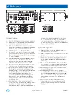
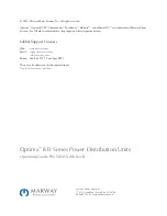
Standard Features
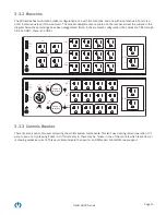
(1) Main 24/30 A breaker and phase-power indicators.
(2) Branch 16/20 A circuit breakers for outlets. Some
models have 5, some models have 6.
(3) Ethernet, RS-232 serial console, and auxiliary
connections. All are RJ-45. Auxiliary connectors are
for Marway Temperature/Humidity sensors.
(6) Internal controls 1 A, push-type breaker.
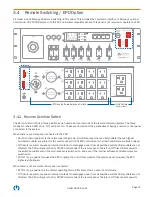
(7) Remote EPO mode switch. A three-position toggle
provides manual control over the remote EPO mode.
See
“3.4 Remote Switching / EPO Option” on page
for a description.
(8) Front panel remote EPO control bus interface. Two
connectors enable the PDU to be daisy chained
between a remote EPO panel (such as Marway’s
UCP) and another PDU, or between two PDUs.
(9) Rear panel remote EPO interface. A third connector
for when a rear connection is more convenient.
(10) Rear panel remote EPO delay interface. When the
Enable signal of a remote panel is triggered, the
signal is propagated immediately to all downstream
devices through the connectors J20, J21, and
J22. Connector J23 introduces a delay of 2
seconds before forwarding the Enable signal. By
daisy chaining PDUs with the delay connectors,
a staggered start can be created between each
downstream PDU.
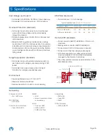
(16) Mounting brackets. May be mounted to yield a
“flush,” front-recessed, rear-facing, or rear-recessed
position of the chassis relative to the rack’s
mounting flanges. The brackets include a cutout to
allow an inlet cable to be directed into the interior
of the rack when the brackets are mounted for a
recessed-chassis position. The brackets may also
be removed for table top operation, or adaptation of
the end user’s own brackets.
Optional Configurations
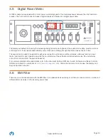
(4) Digital display of inlet power data and relay state.
Included with inlet power option.
(5) Display navigation keypad. Included with inlet power
option.
(11) Power inlet. Some models include a strain-relieved
9-foot cable with an L21-30 plug (front or rear).
Some models include a recessed male connector
(front only).
(12) An pair of unswitched 5-20R outlets are standard
on all models. The location of these outlets and the
Inlet connector (11) are swapped on some models.
(13) All models include at least twelve 5-20R switched
outlets (J1 through J12).
(14) On some models, J13 and J14 are twist lock
connectors with a choice of L5-20, L5-30, L6-20, or
L6-30 where both are the same. On other models,
these two twist locks are replaced by four switched
5-20R outlets (for a total of 16 switched 5-20R
outlets).
(15) Models which include twist locks for J13 and
J14 will also include J15 which is always an L21-
30 providing pass-through power from the main
breaker.
15.93"
0.75"
CB 7
CB 5
OFF
ON
OFF
ON
Input
Main Breaker
CB 1
A
B
C
OFF
ON
CB 2
OFF
ON
CB 3
OFF
ON
CB 4
OFF
ON
OFF
ON
OFF
ON
Ethernet Serial
Aux 1
Aux 2
Ethernet Serial
Aux 1
Aux 2
Values
Devices
Menu
Optima RCM
J 22
Enable
Disable
Return
J 15
(Main)
J 13
(CB 4)
J 14
(CB 5)
Choice of
twist-lock
Choice of
twist-lock
J 23
Delay
Disable
Return
J 4
(CB 1)
J 8
(CB 2)
J 12
(CB 3)
J 1
J 5
J 9
J 16
(CB 7)
J 17
Input
Front Only
19.00"
17.12"
1.75"
1.75"
3.47"
1
2
6
8
7
4
5
3
11
16
12
14
13
15
9
10
Optional Inlet Connectors
Input
Front or Rear
EPO Only
Off
Remote
Remote Override
Controls
Breaker
PRESS
RESET
Enable
Disable
Return
J 20
J 21


