Marway Optima 833 Series Operating Manual And Reference Download Page 11

Page 11

Optima 820 Series

3.4 

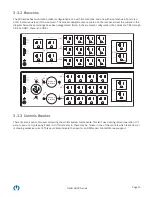
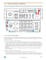
Remote Switching / EPO Option

All model include Marway’s Remote Switching / EPO system. This includes the controls to interface to Marway’s optional 

Commander UCP 5000 Remote On/Off/EPO and similar compatible panels. This panel is not required to operate the PDU.

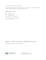
EPO and Software Switched Outlets

CB 7

CB 5

OFF

ON

OFF

ON

Input

Main Breaker

CB 1

A

B

C

OFF

ON

CB 2

OFF

ON

CB 3

OFF

ON

CB 4

OFF

ON

OFF

ON

OFF

ON

Ethernet Serial

Aux 1

Aux 2

Ethernet Serial

Aux 1

Aux 2

Values

Devices

Menu

Optima RCM

J 22

Enable
Disable
Return

J 15

(Main)

J 13

(CB 4)

J 14

(CB 5)

Choice of

twist-lock

Choice of

twist-lock

J 23

Delay
Disable
Return

J 4

(CB 1)

J 8

(CB 2)

J 12

(CB 3)

J 1

J 5

J 9

J 16

(CB 7)

J 17

EPO Only

Off

Remote

Remote Override

Controls

Breaker

PRESS

RESET

Enable

Disable

Return

J 20

J 21

Utility Outlets

(front or rear)

3.4.1 

Remote Override Switch

The 

Remote Override

 is a three-position switch used as a local override to the remote command system. The three 

modes are labeled 

EPO Only

, 

Off

, and 

Remote

. These are named from the perspective of having a remote control panel 

connected  to the system.

When there is a remote panel connected to the PDU:

• 

Remote

 (down position) is the normal operating mode. All outlets except the two utility outlets (the two highest 

numbered outlets) are subject to the remote panel On/Off/EPO controls (and, the internal software-controlled relays).

• 

Off

 (center position) causes an internal contactor to disengage power from all switched outlets. Utility outlets are not 

affected. The PDU will ignore the On/Off/EPO commands of the remote panel. Therefore, 

Off

 disconnects power to 

the switched outlets even if the main breaker is switched on, and even if the internal software-controlled relays are 

switched on.

• 

EPO Only 

(up position) causes the PDU to ignore the On/Off commands of the remote panel. However, the EPO 

signal is still allowed.

When there is not a remote control panel connected:

• 

EPO Only

 (up position) is the normal operating mode. Effectively, this is a Local Control mode.

• 

Off

 (center position) causes an internal contactor to disengage power from all switched outlets. Utility outlets are not 

affected. The PDU will ignore the On/Off/EPO commands of the remote panel. Therefore, 

Off

 disconnects power to 

Summary of Contents for Optima 833 Series

Page 1: ...Optima 833 Series Power Distribution Units Operating Guide and Reference Sep 2021 P N 501055 000 Rev B ...

Page 2: ... 1 Installation Notes 7 3 Operation 8 3 1 Startup 8 3 1 1 Startup Without Configuring the Software 8 3 1 2 Startup to Configure the Software 9 3 2 Ethernet and Serial Control 9 3 3 Breaker Controls 9 3 3 1 Main Breaker 9 3 3 2 Branches 10 3 3 3 Controls Breaker 10 3 4 Remote Switching EPO Option 11 3 4 1 Remote Override Switch 11 3 4 2 Remote Bus Connector 12 3 5 Digital Power Meter 13 3 6 EMI Fil...

Page 3: ... signal cabling Do not open this product as it contains no user serviceable parts inside All service concerns should be directed to Marway Power Solutions If this product is used in a manner which does not comply with this instruction manual the protection provided by the equipment may be impaired All work on connections must be carried out under zero voltage output disconnect and may only be perf...

Page 4: ...s ce produit car il ne contient aucune pièce réparable par l utilisateur Tous les problèmes de service doivent être adressés à Marway Power Solutions Si ce produit est utilisé d une manière non conforme au présent manuel d instructions la protection fournie par l équipement peut être compromise Tous les travaux sur les connexions doivent être effectués sous une tension nulle et ne doivent être eff...

Page 5: ...pace in an EIA 310 compliant rack enclosure This documentation is about the hardware elements of the Optima 833 Series of PDUs For detailed information about the software you ll need the Optima RCM User Guide Software and Basic Controls Reference located on our website at http www marway com docs 1 6 Product Models Models are primarily organized by what type of power inlet they have Then by the ou...

Page 6: ...uplex receptacle 120 Vac 1ɸ 16 A continuous 20 A max per NEMA L5 20R receptacle 120 Vac 1ɸ 24 A continuous 30 A max per NEMA L5 30R receptacle 208 Vac 1ɸ 16 A continuous 20 A max per NEMA L6 20R receptacle 208 Vac 1ɸ 24 A continuous 30 A max per NEMA L6 30R receptacle 120 208 Vac 3ɸ 24 A continuous 30 A max per NEMA L21 30R receptacle 24 A continuous 30 A max total per phase regardless of receptac...

Page 7: ... the Main Breaker on the front of the PDU is in the off position before connecting the PDU s inlet cable to the facility power source It is best to switch all breakers to the off position 6 Facility Power Source The single phase facility power source for this product must include an overcurrent protective device capacity as defined in the table below Main Inlet Continuous Current Rating Mains Prot...

Page 8: ...ith the main circuit breaker Off as soon as the inlet of the PDU is plugged into a live facility outlet the control system of the PDU is powered and the software will start running 3 1 1 Startup Without Configuring the Software It is assumed the PDU is not plugged into the facility power source 1 Switch all breakers on the PDU control panel to the Off position 2 Whether there is a remote EPO panel...

Page 9: ...s and other software features of the PDU Obtain that document and review the Getting Started chapter In effect prepare the Serial and Ethernet connections to the PDU as described in the Software Guide then use the startup process described above in 3 1 1 Startup Without Configuring the Software on page 8 3 2 Ethernet and Serial Control The document Optima RCM User Guide Software and Basic Controls...

Page 10: ...lay Disable Return J 17 J 1 J 4 CB 1 J 13 CB 4 J 15 J 14 J 16 J 8 CB 2 J12 CB 3 J 5 J 9 J 18 CB 5 J 22 Enable Disable Return J 15 Main Choice of twist lock Choice of twist lock J 23 Delay Disable Return J 1 J 5 J 9 J 16 CB 7 J 17 J 13 CB 4 J 14 CB 5 J 4 CB 1 J 8 CB 2 J 12 CB 3 3 3 3 Controls Breaker There is a small pop out breaker protecting the control system components This isn t used during no...

Page 11: ...ese are named from the perspective of having a remote control panel connected to the system When there is a remote panel connected to the PDU Remote down position is the normal operating mode All outlets except the two utility outlets the two highest numbered outlets are subject to the remote panel On Off EPO controls and the internal software controlled relays Off center position causes an intern...

Page 12: ...ice of twist lock Choice of twist lock J 23 Delay Disable Return J 4 CB 1 J 8 CB 2 J 12 CB 3 J 1 J 5 J 9 Input J 22 Enable Disable Return J 15 Main J 13 CB 4 J 14 CB 5 Choice of twist lock Choice of twist lock J 23 Delay Disable Return J 4 CB 1 J 8 CB 2 J 12 CB 3 J 1 J 5 J 9 Input J 22 J 23 Enable Disable Return Delay Disable Return J 17 J 1 J 4 CB 1 J 13 CB 4 J 15 J 14 J 16 J 8 CB 2 J12 CB 3 J 5 ...

Page 13: ...l outlets plus the internal control system It will update approximately every 3 seconds rotating through the three phases one at a time The keypad can be used to navigate through power values for volts amps watts voltamps voltamps reactive power factor and Hertz for each phase as well as the on off status of the software controlled outlet relay The outlet relay cannot be controlled from the keypad...

Page 14: ...a recessed chassis position The brackets may also be removed for table top operation or adaptation of the end user s own brackets Optional Configurations 4 Digital display of inlet power data and relay state Included with inlet power option 5 Display navigation keypad Included with inlet power option 11 Power inlet Some models include a strain relieved 9 foot cable with an L21 30 plug front or rea...

Page 15: ...it Inlet Voltage and Current All models 120 208 Vac 50 60 Hz three phase wye All models 24 A continuous load 30 A maximum Overload Protection standard All models include a four pole main circuit breaker wired with all three phases and neutral passing through the breaker All branch breakers are UL 489 16 A continuous load 20 A maximum Based on NEC regulations traditional load ratings are de rated t...

Page 16: ...DC are trademarks of Marway Power Systems Inc All other trademarks are the property of their respective owners Global Support Contacts Web www marway com Email support marway com sales marway com Phone 800 462 7929 7am 5pm PST There may be updates to this documentation at http www marway com docs Marway Power Solutions 1721 S Grand Ave Santa Ana CA 92705 800 462 7929 marway marway com ...

Reviews: