


Page 9
Optima 829 Series
3.1.2 Startup to Configure the Software
The document
Optima RCM User Guide : Software and Basic Controls Reference
is the complete resource for the process of configuring the network settings, and other software
features of the PDU. Obtain that document, and review the Getting Started chapter.
In effect, prepare the Serial and Ethernet connections to the PDU as described in the
Software Guide
, then use the
startup process described above in
“3.1.1 Startup Without Configuring the Software” on page 8
3.2 Ethernet and Serial Control
The document
Optima RCM User Guide : Software and Basic Controls Reference
is the complete resource for how to setup, configure, and operate the Optima RCM software over serial,
Telnet, SSH, HTTP, SNMP, and RESTful API.
The Ethernet connection supports 10/100 Base-T, IPv4 DHCP and manual addressing. It is recommended to use a
manual address, or DHCP in conjunction with MAC ID reservations so that the IP address stays consistent.
The Serial interface is RS-232 implemented in an RJ45 connector. A protocol conversion cable with a USB connection at
one end and an RJ45 at the other end is ideal for connecting a computer to the Serial port. Marway offers these cables as
part number 311118-000. They can also be found on many online cable retailer web sites.
3.3 Breakers
Various models have one or two breakers.
When there is a single breaker, in effect this behaves like a main breaker, protecting the whole unit, and providing on/off
control for the whole unit.
When there are two breakers, each breaker protects one group of outlets. Outlets are organized into identical groups.
Following the length of the PDU from the inlet, the first breaker operates the first group of outlets, etc.
Each breaker has it’s own indicator. When lit, power is being supplied to the correlating outlet group.
All models use 2-pole breakers with both line and neutral routed through the breaker.
3.4 Digital Power Meter Option
If the PDU is equipped with an inlet power monitoring system, the front control panel will include a digital display and
keypad.
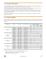
The display will default to showing the amperage being drawn by the system as a whole (all outlets, plus the internal
control system). It will update approximately every 3 seconds.
The keypad can be used to navigate through power values for volts, amps, watts, voltamps, voltamps reactive, power
factor, and Hertz.
For complete display and keypad details, refer to the document
Optima RCM User Guide : Software and Basic Controls
Reference
located on our website at
Obtain that document, and review the Display and
Keypad Operation c