Copyright © 2009 Marvell
Doc. No. MV-S105540-00, Rev. --
March 4, 2009, Advance
Document Classification: Proprietary Information
Page 27
Signal Description
Pin Description
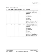
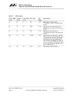
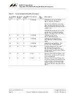
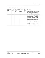
Table 12:
Clock/Configuration/Reset/I/O
117-TFBGA
Pin #
96-BCC
Pin #
128-PQFP
Pin #
Pin Name
Pin
Type
Description
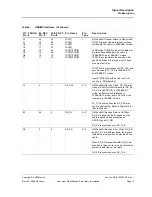
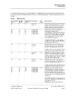
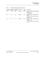
K2
22
31
125CLK
O
Clock 125. A generic 125 MHz clock refer-
ence generated for use on the MAC device.
This output can be disabled via DIS_125
through the CONFIG[3] pin.
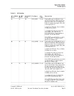
D8
65
88
CONFIG[0]
I
CONFIG[0] pin configures PHY_ADR[2:0]
bits of the physical address.
Each LED pin is hardwired to a constant
value. The values associated to the CON-
FIG[0] pin are latched at the de-assertion of
hardware reset.
CONFIG[0] pin must be tied to one of the
pins based on the configuration options
selected. They should not be left floating.
For the Two-Wire Serial Interface (TWSI)
device address, the lower 5 bits, which are
PHYADR[4:0], are latched during hardware
reset, and the device address bits [6:5] are
fixed at ‘10’.
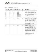
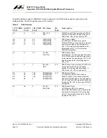
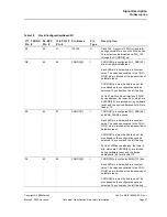
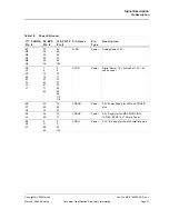
E9
64
87
CONFIG[1]
I
CONFIG[1] pin configures PHY_ADR[4:3]
and ENA_PAUSE options.
Each LED pin is hardwired to a constant
value. The values associated to the CON-
FIG[1] pin are latched at the de-assertion of
hardware reset.
CONFIG[1] pin must be tied to one of the
pins based on the configuration options
selected. They should not be left floating.
For the TWSI device address, the lower 5
bits, which are PHYADR[4:0], are latched
during hardware reset, and the device
address bits [6:5] are fixed at ‘10’.
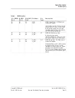
F8
63
86
CONFIG[2]
I
CONFIG[2] pin configures ANEG[3:1] bits.
Each LED pin is hardwired to a constant
value. The values associated to the CON-
FIG[2] pin are latched at the de-assertion of
hardware reset.
CONFIG[2] pin must be tied to one of the
pins based on the configuration options
selected. They should not be left floating.

