7
COPYRIGHT © 2002 MARTIN DOOR
OPENER HEADER
BRACKET
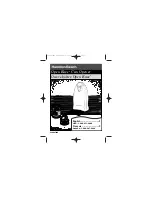
FIGURE 2
OPENER DOOR
BRACKET
CURVED POWER ARM
THIN VERTICAL MARK
THIN
HORIZONTAL
MARK
FIGURE 1
OPENER DOOR
BRACKET
CURVED POWER ARM
THIN VERTICAL MARK
TEMPORARY TIE
TEMPORARY TIE
5/16” X 2” LAG SCREWS
1/4” X 1” THREAD
FORMING SCREWS
1/4” X 1” THREAD
FORMING SCREWS
CENTER MOUNT
CENTER MOUNT
INSTALLATION INSTRUCTIONS FOR A MARTIN DC3700 GARAGE DOOR
OPENER SYSTEM
THESE INSTRUCTIONS ARE INTENDED FOR PROFESSIONAL GARAGE DOOR
OPENER INSTALLERS. READ THROUGH THE COMPLETE INSTRUCTION MANUAL AND
APPLICABLE SUPPLEMENTAL INSTRUCTIONS BEFORE BEGINNING.
STEP 1
FASTENING THE OPENER DOOR BRACKET
Study
"Opener Door Bracket Guidelines” on page 6.
Decide
if the opener will be mounted to the center, off center or side of the garage door.
Center and off center mounted openers always require a “full width” top strut on the door. If
side mounted, Martin Doors up to 12'2" (3700) wide may or may not require a top strut.
Fasten
the opener door bracket under the top roller bracket for side mounting or on the
stile and strut for center/off center mounting. Fasten with 1/4” x 1” Thread Forming Screws.
Fasten
the curved power arm to the opener door bracket with 3/8" X 1" short neck carriage
bolt and two 3/8" lock nuts as shown in the “Opener Door Bracket Guidelines” on page 6.
Raise
the curved opener power arm straight up and touch the torsion tube or spring. Make
a vertical mark on header, in line with the power arm. This mark will be the vertically
centered location for the opener header bracket. See Figure 1
Note: To hold the top of the curved power arm from falling down, temporarily tie it to the top
of the door bracket or strut. See Figure 1
Make
a horizontal mark on the header 2" (51) above the highest movement of the door as
it opens. See figure 2.
The following are approximate measurements above the top of a closed door to the
horizontal mark on the header:
11 1/2" (292)
for 12” (305) regular clearance track.
6 1/2" (165)
for 8" (203) low clearance track.
5" (127)
for 4 1/4" (108) low clearance track.
3 1/2" (89)
for 2 ½" (64) low clearance track.
Fasten
the opener header bracket to the header with two 5/16" X 2" lag screws. The
vertical and horizontal marks are the “centered location” marks.
STEP 2
FASTENING THE OPENER HEADER BRACKET
11 ½” (292)
Regular Clearance
TOP OF
CLOSED DOOR
3/8” X 1” SHORT NECK
CARRIAGE BOLT AND
2- 3/8” LOCK NUTS
HEADER
HEADER
REQUIRED
“FULL WIDTH”
TOP STRUT
REQUIRED
“FULL WIDTH”
TOP STRUT