background image

Manufactured in Great Britain by: 

Marshall Amplification plc, Bletchley, 

Milton Keynes, England.

Model No. JFX-1

WARNING! No user servicable parts inside;
refer servicing to qualified personel only.

Power

9V AC

1.2A

In

MIDI

THRU

Out

Remote

Right

Left

Input

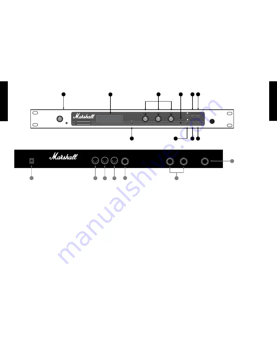
8.  Quit Key :

Takes you back to the original program number

and name from any point in the programming chain.

9.  System Key :

Takes you into the SYSTEM menu. Using the Up

& Down keys to indicate the sub-menu required, the
System key will take you to the REMOTE JACK
on/off selection.  MIDI section where each press of the
key will show the next MIDI function to be
programmed until you return to the initial system
menu; and the BATTERY LEVEL indicator.

10.  Store Key :

Stores all edited parameters to the selected program

location. Press once to display the program location
number-press again to complete the store.

* Note :

The JFX-1 features touch sensitive push keys.  A

single press will provide a single step increment,
maintained pressure will provide a fast scroll through.

3.1 - Rear Panel

1.  Input Jack :

Input to accept the signal sent from your amplifier,

pre-amp or mixing desk.

2.  Output Jacks ( Left & Right ) :

Stereo output from the JFX-1 to connect to the

return inputs of your amplifier, pre-amp or mixing
desk.

3.  Remote Jack :

When using an amp or combo with Channel

switching facilities, connecting a lead from this output
to the footswitch input of the amplifier, allows you to
switch channels as you switch programs on the JFX-1.

4.  MIDI OUT :

Sends out-going MIDI messages from the JFX-1.

5.  MIDI THRU :

Sends out MIDI messages identical to those

coming in through the MIDI IN terminal.

6.  MIDI IN :

Terminal to receive incoming MIDI messages from

any external MIDI device.

7. Power Supply Input :  

Accepts the input from the remote power supply

provided with the JFX-1.  Always ensure that only this
power supply is utilised.

Section 3 - Front Panel

1.  Input Level & Peak LED :

Controls the level of the signal coming into the

JFX-1. The optimum signal level is reached when the
peak LED lights occasionally.

2.  Display Window :

This LCD display provides the interface between

you and the JFX-1 by displaying the current status of
all operating and programming functions in 2 lines of
16 characters each.

3.  Toggle Switch :

Pressing the Toggle Switch at any time displays the

output levels of the Direct and Effects signal. The
Direct level is adjusted using DATA Control 

and the

Effects level using DATA Control 

. Both range from

00-99.  Pressing ‘Toggle’ a second time returns you to
the point in the program from where the initial toggle
selection was made.

4.  DATA Controls :

Only operational when the JFX-1 is in Edit mode.

DATA Control 

- Adjusts the first parameter to be

edited.  DATA Control 

- Adjusts the second

parameter to be edited.  DATA Control 

- Adjusts the

third parameter to be edited.

5.  Edit LED :

The LED indicates red only after any program

parameter has been adjusted, but the program hasn’t
been stored.

6.  Up & Down keys :

Multi function keys which scroll through the stored

programs in normal mode.  When in Edit mode they
move the cursor backward and forward for selections
from the main menu.  They also affect certain sub-
menus such as MODE -where they scroll through the
master modes available. NAME -where they move the
cursor to the desired letter location.

In MULTI-TAP MODE they select the individual

voices 1-6 and relative delay times for each voice.  In
REVERB mode they provide the selection of an
alternative decay character.  In the SYSTEM menu they
switch the Remote Jack on/off plus select the MIDI
Channel on which the JFX-1 receives MIDI data.  They
also provide the master location selections for the Input
and Output mapping and MIDI controllers.

7.  Edit Key :

Puts the JFX-1 into Edit mode. Pressing once

displays the main menu-pressing again displays the
parameters which may be edited.  Each subsequent
press displays any further parameters available for
editing until the display returns to the main menu.

FRENCH

GERMAN

SP

ANISH 

JAP

ANESE

ENGLISH

7

6

FRENCH

GERMAN

SP

ANISH 

JAP

ANESE

ENGLISH

Power

Made in England

Input Level

Peak

D a t a

D a t a

D a t a

S I G N A L   P RO C E S S O R

To g g l e

E d i t

1

3

2

JFX-1

E d i t

S y s t e m

Q u i t

S t o r e

1

2

4

5

7

9

3

2

3

4

5

6

7

1

6

8

10

Summary of Contents for JFX-1

Page 1: ...USER MANUAL ...

Page 2: ... Diagrams A With a Home Recording Mixer B Stereo Rack System C With a Stereo or Mono Combo Amp Section 2 Quick Reference Guide 2 1 Selecting a Stored Pre Set 2 2 Editing Pre Set Programs 2 3 Storing Altered Parameter Values 2 4 Naming a Program Section 3 Front Panel 3 1 The Rear Panel Section 4 The Mixer Section 4 1 Setting the Output Levels Section 5 Chorus Flange Mode 5 1 Chorus Flange Types 5 2...

Page 3: ...al in a safe place for future reference after studying it carefully as gaining a full understanding of how the JFX 1 operates will ensure that you are getting the most from it s processing power especially when designing your own personal sounds Manufactured in Great Britain by Marshall Amplification plc Bletchley Milton Keynes England Model No JFX 1 WARNING No user servicable parts inside refer s...

Page 4: ...splay shows Move the cursor along using the UP and DOWN keys and as it rests under each letter that character can then be altered using the Data control Follow the Store procedure for storing altered parameters by pressing the STORE key once to show the desired program to which the name should be assigned and then a second time to complete the store Once the store function has been completed the E...

Page 5: ...ached when the peak LED lights occasionally 2 Display Window This LCD display provides the interface between you and the JFX 1 by displaying the current status of all operating and programming functions in 2 lines of 16 characters each 3 Toggle Switch Pressing the Toggle Switch at any time displays the output levels of the Direct and Effects signal The Direct level is adjusted using DATA Control a...

Page 6: ...djusted using Data Control Duck 00 99 Ducking allows you to momentarily lessen the amount of effect present in relation to the dry signal in order to keep the sound uncluttered and more intelligible If for example you were using a high level of Chorus on a distorted sound you may want the initial note to remain almost unaffected but as it decays require more effect to come in This is where a high ...

Page 7: ...tion of multiple taps voices taken from a delay line where each voice has it s own individually programmable set of parameters The JFX 1 features 6 stereo voices tappable from a delay line 730 milliseconds long each with modulation to effectively give you the option of creating chorus flange effects with or without delay In addition by making each individual delay and it s position within the ster...

Page 8: ...duced when an accurate reproduction of the input signal is delayed for a specified time usually in milliseconds then fed back to the input to create controllable multiple repetitions The JFX 1 contains three different delay types to produce a multitude of high quality mono stereo or ping pong delays 7 1 Delay types The delay types are all selected using the Data Control Mono The signal can be dela...

Page 9: ...avel Large Hall The Large Hall setting extends the reflections even further and produces the simulation of huge spaces with very high ceilings and extra long decay characters 8 2 Reverb Characters In addition to the four reverb types the JFX 1 also contains four quite distinct programmable reverb characters By careful adjustment of the frequency content of the decay we have made each character equ...

Page 10: ...ypes of master chorus flange selections These are selected using Data Control as follows Mode 1 Mono Chorus Standard mono chorus where the same effect appears at both left and right outputs Mode 2 Stereo Flanger Modulation split so that as one side flanges up the other side flanges down Mode 3 Stereo Chorus Split so that as the de tuning effect appears flat at one output it appears sharp at the ot...

Page 11: ...is factory set to receive it s MIDI commands on all channels Omni but if you wish to select a particular channel the procedure is as follows Press the System key The Display shows Use the Up key to move the cursor until it rests under MIDI Press the System key again The Display shows Use the Up key to scroll through the MIDI channels 01 16 and the Down key to scroll back again This is a global fun...

Page 12: ... key to display the battery level The Display shows When the battery level becomes low The Display shows You should now make arrangements to return the JFX 1 to your nearest authorised service centre for battery replacement and also back up your programs FRENCH GERMAN SPANISH JAPANESE ENGLISH 21 20 FRENCH GERMAN SPANISH JAPANESE ENGLISH 12 5 MIDI Controllers For live performance it can be benefici...

Page 13: ... 470 K Output Impedance 470 Ohms FRENCH GERMAN SPANISH JAPANESE ENGLISH Function Transmitted Recognised Remarks Basic Default 1 Omni Memorised Channel Altered 1 16 1 16 Default x Mode 1 Mode Message x x Altered x x Note x x Number True Voice x x Velocity Note ON x x Note OFF x x After Key s x x Touch Channels x x Pitch Bender x x Control Change x 0 Program 0 127 0 127 Input Output Change True 0 12...

Reviews: