background image

SETTING THE TEMPERATURE

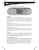
Pressing the temp up or temp down buttons allow you to adjust the heat to 

the desired temperature.  The set temperature is shown in the left hand side 

of the LCD display.  Pressing and holding the temp up or temp down button 

will allow for an accelerated change of the temp.

Factory default temp - 100°F (38°C)

Maximum set temperature - 104°F (40°C)

Minimum set temperature - 60°F (16°C)

CHANGING THE SYSTEM SETTINGS

A few basic keystrokes will allow for easy navigation of the available pro

-

gramming options.  The settings, soak, temp up and temp down buttons 

also serve as side to side and up and down navigation controls when in the 

menu. Note the arrows on the buttons. The back/set button in the center is 

used to save a setting or go back one screen at a time. 

Tip!  Note that the menu item that is selected will be brighter in the display 

than the others indicating where you are in the menu.  

Tip!  If you have accidentally entered the setting menu, simply press the 

back/set button or wait 30 seconds to go back to the home screen.

programming choices shown in the main and sub menus.  (See definitions 

of menu and sub menu items.)

Heat Mode (main menu item) 

• 

Ready

• 

Rest

• 

Time of day (main menu item)

• 

Current set time

• 

Filter cycles (main menu item)

• 

Filter cycle 1 and filter cycle 2

• 

Preferences (main menu item)

• 

Temp display – Choose between Fahrenheit “F” or Celsius “F” 

• 

Time display – choose between 12 or 24 hour display

• 

Cleanup – choose the length of time of the clean-up cycle

• 

Language – choose between English, Spanish, French or German

• 

Diagnostics (main menu item

• 

Vessel

• 

Information

• 

A/B Temps

• 

Fault Log

• 

To make a change, perform the following sequence 


Press the setting button to display the main settings menu

• 

Press the settings button to move over into the main settings menu

• 

Scroll down by pressing the temp down button to the desired menu 

• 

item

Press the settings button to move into the sub menu

• 

Press the temp up or temp down to change the parameters (note if a 

• 

change is made, the save and cancel icons appear on the left hand side 

of the screen).

operating your atv

Summary of Contents for ATV-14

Page 1: ..._________ Date of Purchase ________________________________________________________ Address _________________________________________________________________ City _________________________________Stat...

Page 2: ...S ATV 14 MODEL 12 ATV ZONES 13 14 STARTING YOUR ATV 15 16 OPERATING YOUR ATV 17 18 MARQUIS ATV CONTROL OPERATION ATV 14 19 22 Audio System 22 Swim Tether 23 MARQUIS ATV EQUIPMENT DIAGRAM ATV 14 24 MAR...

Page 3: ...the equipment compartment This connector should be bonded with a minimum 2 5mm solid copper wire between this unit and any metal ladders metal water pipes metal enclosures of electrical equipment con...

Page 4: ...lt Lower water temperatures are recommended for extended use exceeding 10 minutes and for young children When used for prolonged exercise periods lower water tem peratures of 85 F 29 C to 88 F 31 C ar...

Page 5: ...ildren must not be allowed to climb onto the vessel cover All Marquis vessels are equipped with a locking cover that meets the ASTM F1346 91 Standard for Safety Covers Always lock the child resistant...

Page 6: ...ure to perceive heat failure to recognize the need to exit the vessel physical inability to exit the vessel fetal damage in pregnant women and unconsciousness resulting in a danger of drowning Other b...

Page 7: ...the high limit thermostat which will turn off the entire vessel PERSONAL SAFETY DO NOTs Don t use the vessel with the equipment compartment door removed Don t use the vessel for more than 10 minutes...

Page 8: ...T be installed to permit access for servicing the equipment above and or below any decks or floors Access is essential and must allow adequate room for service To facilitate repairs Marquis Corp or it...

Page 9: ...ng wire per national and local electrical code INDOOR INSTALLATION There are special requirements if you place your vessel indoors A flat level concrete reinforced pad at a minimum thickness of 152mm...

Page 10: ...nging when or how long the pumps will run See VESSEL CONTROL OPERATION for available options FILTER CARTRIDGES Your vessel is equipped with the ConstantClean Filtration system It fea tures one long fi...

Page 11: ...be made in accordance with the wiring diagram found on the inside of the control box cover Connections must be made with copper conductors only do NOT use aluminum wire All conductors circuit breaker...

Page 12: ...ights 12 15 Interior LED Lights optional 12 16 Control Panel 1 19 Rowing Rod Mounting Plate 2 20 Rowing Band Clip 2 21 Swim Tether Plate 1 22 Grab Rail 1 23 Vortex Filter 2 24 Speakers optional 4 25 H...

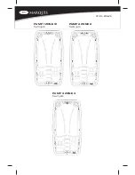
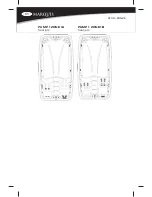
Page 13: ...atv 14 zones PUMP 1 ZONE 1C Swim jets PUMP 2 ZONE 2 Swim jets PUMP 3 ZONE 3 Swim jets...

Page 14: ...atv 14 zones PUMP 1 ZONE 1A Seat jets PUMP 1 ZONE 1B Seat jets...

Page 15: ...IS IMPORTANT for your safety and the longevity of your vessel In the case of relocating your vessel it is impera tive to follow the instructions in the owner s manual These instructions must remain w...

Page 16: ...he pump unions located behind the equipment door After turning the power on again the vessel initiates a new priming mode Repeat steps above 10 The system requires approximately two minutes of water f...

Page 17: ...ck half and then off the vessel providing full access Because of the size of the vessel and cover it is highly recommended to have cover lift as sists attached to the vessel to aid removal NOTE Unlock...

Page 18: ...ry to run without any additional programming changes other than setting the desired temperature We do however recommend that the time is set as this will be shown in the dis play as a convenience and...

Page 19: ...speed Pressing the button a third time will turn the pump off The pump will run for 15 minutes before shutting off or switching to low speed Light Pressing the light button will turn the LED lights on...

Page 20: ...ly entered the setting menu simply press the back set button or wait 30 seconds to go back to the home screen Programming choices shown in the main and sub menus See definitions of menu and sub menu i...

Page 21: ...viewed and not changed Typically these functions will be used by a service technician but can be helpful to the owner when reporting an issue to the dealer or service technician over the phone Wi Fi...

Page 22: ...tion Do not connect any auxiliary com ponents for example cable additional speakers headphones additional audio video components etc to the system except as provided by the following The 3 5 mm auxili...

Page 23: ...he body such as crossing one s legs should be avoided Abnormal rotation of the hip especially internal rotation can lead to dislocation Consult your physician prior to starting ANY type of exercise pr...

Page 24: ...p your vessel cover closed when the vessel is not in use This helps prevent unwanted debris from entering the vessel and prevents sun exposure that could damage the surface and the jets of the vessel...

Page 25: ...e and Filter Cleaner to treat the filters Note Keep an extra filter on hand so you always have a clean one ready for immediate vessel enjoyment Remember to replace the filter cartridge at least once a...

Page 26: ...oing so could result in damage to the drain valve due to freezing water Clean the Interior Surface Once the vessel is drained clean the interior surface thoroughly especially at the water line We sugg...

Page 27: ...l or bleach 1 Remove the cover from the vessel and gently lean it against a wall or fence 2 Use a garden hose to spray the cover and loosen and rinse away dirt or debris 3 Use a large sponge and or so...

Page 28: ...m place vacuum nozzle over each jet nozzle to remove water from plumbing lines starting with the highest jet and finishing with the lowest jet Note The vessel is equipped with a Tri Zone control which...

Page 29: ...ater only Do not use a dry chemical fire extinguisher to attempt to put out the fire 7 When adding chemicals always keep the water circulating in the vessel with jets in a downward circular pattern fo...

Page 30: ...The water must be balanced so the sanitizer can work and vessel equipment is protected 2 SHOCK Shock to oxidize organics and maximize sanitizer efficiency 3 SANITIZE Maintain a proper level of sanitiz...

Page 31: ...s between 200 300 ppm The calcium hard ness is normally adjusted when filling or refilling after draining the ves sel High calcium levels can cause scale buildup on vessel surfaces and equipment Your...

Page 32: ...ularly will not have an odor SANITIZE ConstantClean System The ConstantClean system utilizes a combination of sanitizers to in crease water quality and significantly decrease maintenance The factory i...

Page 33: ...ical damage you will be charged at the regular service rate P Problem S Solution Cloudy Water P Inadequate filtration or dirty filter S Ensure that the filter is securely installed Clean or replace fi...

Page 34: ...o see if desired level has been reached Adjust Spa Frog bromine to reduce bromine level High Sanitizer Reading P Too much chlorine or bromine added or dispensed into the vessel S Remove vessel cover a...

Page 35: ...arranted against cracking and peeling for five years The ozonator is warranted against defects in material and workmanship for two years If equipped LED lights RF sensors remote controls valves ATV co...

Page 36: ...our ATV Other items not included in this warranty are freight expenses labor and material cost associated with removal and or replacement of the ATV damage to or fading of the ATV surface and staining...

Page 37: ...is defined as any component change electrical conversion or the addition of any alternative sound system components which contribute to component failure Misuse and abuse shall include without limitat...

Reviews: