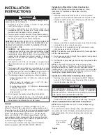
Instalación y conexionado del conjunto calefactor /
ventilador
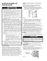
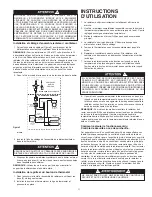
1. Siguiendoeldiagramadeconexionado(Figura3),conectelos
conductoresdealimentaciónaloscablesdeconexióndelcalefactor
situadosenlacajaposterior.
NOTA:
paraloscalefactoresde120Vy277Vconecteelcablede
alimentaciónblanco(neutro)alconductorflexibleblancodelcalefactor,y
conecteelcabledealimentaciónnegroalconductorflexiblenegrodel
calefactor.Paracalefactoresde208yde240volts,cambieelcolordel
conductorflexibleblancodelcalefactoranegro,envolviéndoloencinta
eléctricanegra.(Lamayoríadeloscódigoseléctricosrequierenquelos
cablesdealimentaciónseconectenacablesdeconexiónnegros).
Luegoconectelosdoscablesdealimentaciónnegrosalosdoscables
detomacorrientenegros.
2. Asegureelconductordetierradelaalimentacióneléctricabajoel
tornilloverdedepuestaatierradelacajaposterior.
3. Inserteelenchufedecablesquevienedelconjuntodecalefactor/
ventiladoraltomacorrientedelacajaposterior.
4. Acomodeelconjuntocalefactor/ventiladorenlacajaposterior,y
sujételoensuposiciónconlosdos(2)tornillosprovistos,atravésde
lasranurascentralesdelconjuntodeventilador.
NOTA:
uselostornillosprovistosporlafábricaparainstalarla
plataformadelventiladorenlacajaposterior.
Instalación de la rejilla y de la perilla del termostato
1. Sujetelacubiertafrontalalconjuntodecalefactorpormediodelos
dos(2)tornilloslargossuministrados.
2.Coloquelaperilladeltermostatosobreelejedeltermostatoy
presiónelahastasuposición.
INSTRUCCIONES DE
OPERACIÓN
1. Elcalefactordebeinstalarsecorrectamenteantesdeponerloen
funcionamiento.
2. Despuésdequeelcalefactorestémontadoporcompleto,hagagirar
laperilladeltermostatoensentidoantihorariohastaqueelcontrol
llegueauntope.Estaeslaposicióndecalormínimo.
3. Conectelaalimentacióneléctricaalcalefactoreneltablerode
distribuciónprincipal.
4. Enesascondiciones,elcalefactornodebefuncionar.Sifunciona,
desconectelaalimentacióneléctricayvuelvaainspeccionarel
conexionado.
5. Hagagirarlaperilladeltermostatoensentidohorariohastaque
llegueauntope(posicióndecalormáximo).
6. Elcalefactoryelventiladordebenencenderse.Sielcalefactoryel
ventiladornoentranenfuncionamiento,desconectelaalimentación
eléctricaeinspeccioneelconexionado.
7. Dejequeelcalefactorcontinúefuncionandohastaquela
temperaturaambientealcanceelniveldeconfortdeseado.Luego
hagagirarlaperilladeltermostatolentamenteensentido
antihorario,hastaqueseescucheel‘clic’queindicaqueel
termostatoapagóelcalefactor.
8. Puedequeseanecesariovolveraajustareltermostatounaomás
veceshastaquesealcanceelniveldeconfortexacto.Larotaciónen
sentidohorarioaumentaráeltiempoduranteelcualelcalefactor
producirácalor.Larotaciónensentidoantihorarioreduciráeltiempo
duranteelcualelcalefactorestáencendido.
NOTA:
paraobtenerlosmejoresresultados,elcalefactordebe
permanecerconstantementeEncendido(‘ON’)durantelatemporadaen
quesenecesitecalefacción,yaqueeltermostato,siemprequeesté
correctamenteajustado,mantendrálatemperaturadeseada.Enla
posiciónextremaensentidoantihorario,elcalefactorpermanecerá
Apagado(‘OFF’)hastaquelatemperaturadelahabitacióndisminuya
bienpordebajodelpuntodecongelación.
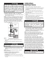
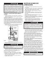
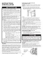
Cómo efectuar la reposición del control de seguridad
contra sobretemperatura:
Estecalefactorestáprovistodeuncontroldeseguridaddeexcesode
temperaturaconunfusibletérmicodeseguridad.Elcontrolde
seguridadseconvertiráenunaadvertenciarojaluz,visibleatravésde
lapartedelanteradelarejilla,seiluminaráparaalertaralpropietario
quelaestufaestéapagadayrequiereatención.Botóndereiniciode
estecontrolseencuentradetrásdelarejillaporencimadelaluzrojade
advertencia.Elbotónrojodereposiciónpuedeverseatravésdela
rejillafrontal,cuandoseinstalaelcalefactor.Paraefectuarlareposición
espereaqueelcalefactorseenfríe;luego,conunobjetoquepasea
travésdelascelosías(comoundestornilladorplanopequeño),oprima
elbotóndereposiciónqueesvisibleenelpaneldelventilador.El
calefactordebevolverinmediatamenteasufuncionamientonormal.Sila
luzdealarmapermaneceencendidadespuésdequeelcalefactorseha
enfriadoyelbotóndereposiciónmanualsehapulsado,esposibleque
sehayaactivadoelfusibletérmico.Siestoocurre,elcalefactordebeser
revisadoyreparadoporunelectricistacompetente.
SIELVENTILADORSEAPAGADEINMEDIATO,SIGNIFICAQUEEL
CONEXIONADO DEL TERMOSTATO ES INCORRECTO Y DEBE
MODIFICARSE. ELVENTILADOR DEBE RETARDAR SU APAGADO
PARAEXPULSARELCALORRESIDUAL,AFINDEPREVENIREL
ENVEJECIMIENTO PREMATURO DE COMPONENTES INTERNOS
DELCALEFACTOR,QUEPODRÍAPROVOCARUNRIESGOOUNA
FALLAPREMATURA.
ASEGÚRESE DE QUE TODO EL CONEXIONADO ESTÉ
ENCAMINADO DE FORMA SEGURA, LEJOS DELVENTILADORY
DELELEMENTOCALEFACTOR.
NOUTILICECONESTECALEFACTORUNTERMOSTATOREMOTO.
EL TERMOSTATO INCORPORADO CONECTA Y DESCONECTA
(HACE CICLAR) EL ELEMENTO CALEFACTOR ÚNICAMENTE. EL
CONTROLDERETARDODEVENTILADORENCIENDEYAPAGAEL
VENTILADORAUTOMÁTICAMENTEYPROPORCIONAADEMÁSUN
APAGADOCONRETARDODELVENTILADOR,AFINDEELIMINAR
ELCALORRESIDUALDESPUÉSDEQUEELTERMOSTATOHAYA
APAGADOLOSELEMENTOSCALEFACTORES.ELCONEXIONADO
DEL CALEFACTOR DE CUALQUIER FORMA QUE ANULE LA
FUNCIÓNDEAPAGADOCONRETARDODELVENTILADORPUEDE
PROVOCAR SOBRECALENTAMIENTO Y DAÑOS PERMANENTES
ALCALEFACTOR,YANULARÁLAGARANTÍA.
NOMANIPULAROELUDIRCUALQUIERLÍMITESDECONTROLDE
SEGURIDADDENTRODECALENTADOR
7
ALARM
LIGHT
THERMAL
FUSE
MANUAL
RESET
LIMIT
ALARM
LIGHT
THERMAL
FUSE
MANUAL
RESET
LIMIT
Figura 3
CONEXIONADO
DELACAJA
POSTERIOR
*BLANCO PARA 120 Y 277 VOLTS
CONJUNTODECALEFACTOR
NEGRO
VERDE
*NEGRO
AzUL
TERMOSTATO
MOTORDEL
VENTILADOR
INTERRUPT
ORDE
DESCON-
EXIÓN
FUSIBLE
TÉRMICO
LUzDE
ALARMA
RETARDODE
VENTILADOR
ELEMENTO
SUPERIOR
ELEMENTOINFERIOR
LÍMITE
TÉRMICOCON
REPOSICIÓN
MANUAL
NEGRO
AzUL
NEGRO


