
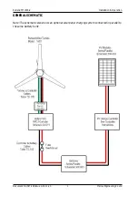


Rutland FM1803-2
Installation & Operation
Document No: SM-146 Issue G 01.11.20
Marlec Engineering Co Ltd
4
General warnings
•
The generator is fitted with rare earth magnets which can be damaged by heavy handling.
The main generator assembly should be treated with care during transit and assembly.
•
Do not adjust the settings on the controller without reference to the manufacturer.
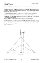
Working at height—use suitable equipment. Effect as much of the installation at ground level
as possible and choose a calm day to install the turbine.
If in doubt refer to your dealer, a competent electrical engineer or the manufacturer
.
CHECK YOU HAVE RECEIVED
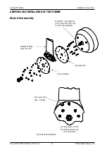
Three (3) Aerofoil Blades and 9 nuts and bolts
Main Generator Assembly
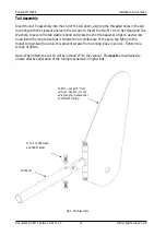
Tail Fin assembly and Fixings
Nose Cone and fixing screws
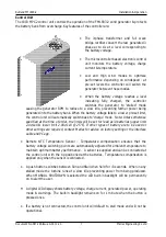
Control Unit – Check that the voltage indicated on the connection label and the side of the
housing corresponds with your battery voltage.
Temperature Sensor – packed with control unit
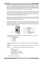
3 Way Connector Block
In the event of loss or damage, consult your dealer or the manufacturer.
WHAT YOU WILL NEED
Tools
Suitable wire stripper
Small terminal screwdriver
Phillips (cross-head) screwdriver
2 x 13mm spanners or sockets
36mm spanner or socket
17mm spanner or socket
8mm Socket key
Other Items You Will Need
Run/Stop Switch supplied separately from Marlec (optional)
Mounting tower & winch or other suitable lifting/pulling equipment
Cables
Batteries & terminals
Connector blocks (as determined by your total system)
Suitable fixings for wall mounting the control unit.
Sensor cables (optional)
Please complete the system details and serial numbers in the maintenance schedule (Appendix
A). This information is important & should be kept safe & available if contacting the
manufacturer for advice or technical information.


