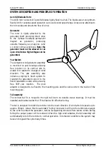


Rutland FM1803-2
Installation & Operation
Document No: SM-146 Issue G 01.11.20
Marlec Engineering Co Ltd
16
CABLE SPECIFICATION
Follow the guidelines for cable sizes in the table below. The type of cable is dependent on the
type of installation and national or local wiring regulations. All cables must be suitably
protected from mechanical damage.
All cables & installation should be in accordance with IEE Wiring regulations
Turbine to Controller
Type
4 equally sized stranded cores. Note the FM1803 is 3 phase AC
output and the connection sequence is in any order and colour.
The earth connects to the earthing point in the controller.
Specification Cable
Run
Minimum Cable Size
(m)
(mm²)
AWG
Up to 50
1.5
16
Up to 100
2.5
14
Up to 150
4
12
Up to 250
6
10
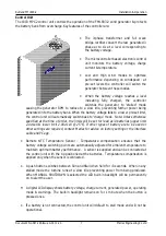
Controller to Battery
Type & Specification
2 separate cores black - and red +, stranded
cable. Minimum 10mm² and
≤
1.5m length.
Remote Temperature
Sensor
1.5m cable supplied with controller
Remote Voltage Sensing
Wires
A pair of conductors 0.5 to 0.75mm from the
battery terminals to the controller. Optional to
fit where >1.5m battery cables are used.
Caution! System performance and safety are compromised if smaller cable
sizes are installed and there is risk of electrical damage in high winds.
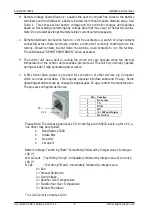
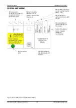
FUSES
A suitably rated fuse may be fitted in the battery “+” line to protect the cables against damage
arising from any accidental reverse polarity connection at the battery.
WARNING! – This fuse will not protect the control unit’s electronics from the high currents that
flow from a reverse polarity event, permanent damage is likely. Note also that a blown fuse will
cause the turbine to run open circuit resulting in further damage to the control unit and
turbine. Place this warning at the fuse:
DO NOT REMOVE FUSE UNLESS THE TURBINE IS STALLED.
Table 2.
System Voltage Minimum Fuse Rating
12V
100A
24V
50A
48V
25A
Table.1


