


3
OPERATING INSTRUCTIONS
____________________________________________________________________________
MODELS:
□
M24E24A
□
M24E32A
□
M24E36A
□
M24E42A
□
M24E48A
□
M36E24A
□
M36E32A
□
M36E36A
□
M36E42A
□
M36E48A
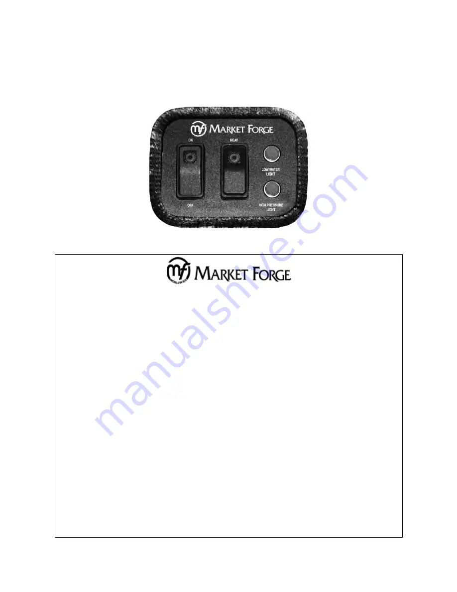
CONTROL PANEL
OPERATING INSTRUCTIONS
STEAM GENERATOR
● FIRST CHECK TO BE SURE THAT:
A.
B.
C.
D.
E.
WATER SWUTCH IS IN THE OFF POSITION.
WATER SUPPLY VALVE IS OPEN.
ELECTRICITY IS CONNECTED TO ALL UNITS.
THAT THE GAS IS TURNED ON (GAS OPERATED UNITS ONLY).
THEN PROCEED EITH DAILY OPERATING PROCEDURES.
DAILY OPERATING PROCEDURE
STEP 1
PRESS WATER SWITCH FROM OFF TO ON.
STEP 2
WAIT 5-10 MINUTES FOR WATER TO FILL IN STEAM GENERATOR
(GAUGE GLASS SHOULD BE 2/3 FULL).
STEP 3
PRESS HEAT SWITCH FROM ON TO OFF AND RELEASE BACK TO ON
WHEN THE LOW WATER LIGHT GOES OFF. GREEN INDICATOR LIGHT WILL
COME ON (THIS IS NECESSARY TO MANUALLY RESET THE UNIT).
DAILY SHUT DOWN AND CLEANING
STEP 1
PRESS WATER SWITCH OFF. THIS WILL DRAIN THE STEAM GENERATOR.
STEP 2
AFTER STEAM GENERATOR HAS COMPLETELY DRAINED REPEAT
STEPS 1 & 2 OF DAILY OPERATING PROCEDURE.
(WATER TO REMAIN IN STEAM GENERATOR UNTIL NEXT DAILY USE)
Summary of Contents for M24E24A
Page 31: ......