
Marine Revolution
Smartwave SW 4200 Owner’s Manual
Page 10
Electrical System
Never:
- Work on an electrical installation which is connected
- Modify an installation and the corresponding wiring diagrams unless this is carried out
by a qualified marine electrician.
- Disconnect the terminals or turn the battery switches off while the engine is running, as
it could result in damage to the engine.
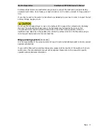
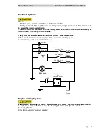
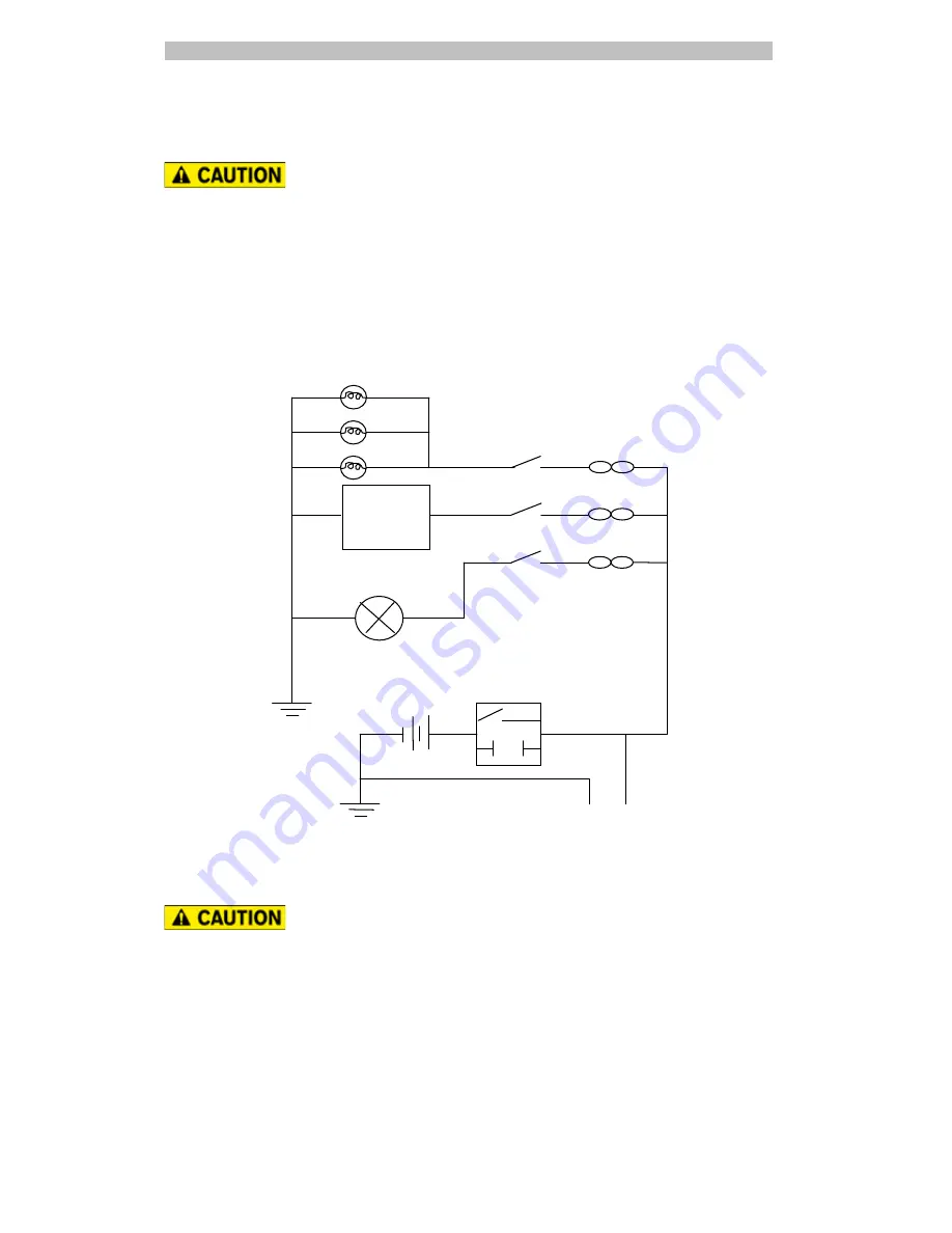
The typical Smartwave SW4200 electrical circuit is described below.
NOTE: Circuit shown includes, Navigation lights, accessories and bilge pump.
Your model may not include all these features.
Engine Cooling System
Ensure water is coming out of the “water check port” every time the engine is started. If
no water is coming out the nozzle, stop the engine immediately and inspect of
blockages/faults.
Refer to manufacturer’s manual supplied.
Bilge Pump
5A Fuse
Batt Isolator
Or
Quick
connector
10A Fuse
10A Fuse
SW1 Nav Lights
SW2 Accessories
SW3 Bilge Pump
Sounder
GPS
VHF
Port Nav
Stb Nav
Stern Nav
12vDC
Engine
Power
Supply