background image

6

The SERAPH M2 in Detail: System settings

6.4

ASIO Device Setup

In the field of professional music production on the PC, the ASIO interface has established
itself as a standard.

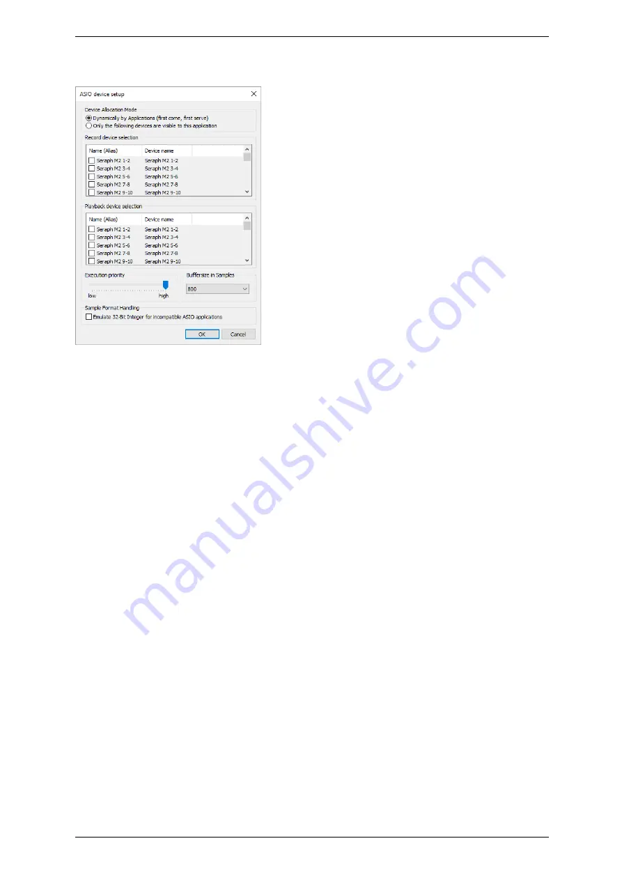
The ASIO device setup offers important setup features for using the

SERAPH M2 with an ASIO interface. It is opened from within the audio application that
supports the ASIO standard. Mostly there is a button called ’control panel’ or ’setup’ near the
selection field for the ASIO driver. Clicking it will open the ASIO device setup.
Here you will see all in- and output devices , which the SERAPH M2 offers. Via default, the
ASIO application may use all in- and output devices of the SERAPH M2, unless a device is
already in use by another application.
Selecting ’Only the following devices are visible to this application’ will allow you to choose
yourself, which device can be used by the application. If an entry is checked, the corresponding
device is active and visible to the application.
Clicking an entry in the column ’name (Alias)’ will allow you to change the name of this in-
or output. This will appear in the same way in the ASIO application. Example: You name
’SERAPH M2 1-2’ to ’guitar’ or ’room mic’. Now in the audio application you will always see
at first glance which signal comes from where.
On the left lower side of the window you can find the ’execution priority’ slider. It can be freely
positioned between ’low’ and ’high’. In position ’high’ the transfer of the audio data between
ASIO application and SERAPH M2 will receive the highest priority. This means, that the
processor will handle this data preferably.
In position ’low’ the calculation of plug in effects will receive the highest priority and the audio
data transfer will be dealt with secondarily. On the lower right side of the window you can find
a selection menu for ’Buffersize in Samples’. This value defines the latency of the audio data
transfer. An example: working with 44.1kHz and setting up 176 samples as buffersize will result
in a latency of 4ms. When working with 88.2kHz, the same buffersize will result in a latency of
2ms.

18

Summary of Contents for SERAPH M2

Page 1: ...SERAPH M2 SERAPH M2 MWX User Manual...

Page 2: ...try to correct the interference by suitable measures c 15th July 2019 v2 0 MARIAN Hardware Design by MARIAN All rights reserved No part of this User s Guide may be reproduced or transmitted in any for...

Page 3: ...media playback program 8 4 3 Using an ASIO music software 8 5 Let s start Recording 10 5 1 Introduction 10 5 2 Using a media playback program 10 5 3 Using an ASIO multi channel music software 10 6 The...

Page 4: ...sound system you can see newest technologies merging with long proven experience and development skills into a powerful DAW Digital Audio Workstation Based on a super fast PCIe interface a single SER...

Page 5: ...the following components are to be found complete and undamaged 3 1 x SERAPH M2 PCIe card 3 1 x MIDI WordClock Externder with connector cable MWX version only 3 1 x cable for MIDI Input output MWX ver...

Page 6: ...update it may become necessary for the firmware of the SERAPH M2 to be updated Whether a firmware update is necessary or not can only be determined after an installation update was performed The firmw...

Page 7: ...2 Before you start 2 3 Connections SERAPH M2 MWX2 optional 4...

Page 8: ...MIDI Sub D Using the included MIDI breakout cable 2 MIDI Inputs and 2 MIDI Outputs may be used WordClock This connector is used to integrate the SERAPH M2 into a WordClock SuperClock network If the SE...

Page 9: ...g at the time of half a second 3 2 2 What is a clock There has to be something that governs at which moment a digital value may be send or received because this is essential for the accurate communica...

Page 10: ...nchronize to the clock of the master and are therefore slaves 5 3 Digital audio connections already include a clock signal S PDIF ADAT MADI or AES EBU Alternatively the synchronization may be accompli...

Page 11: ...n the lower part of the window activate Set Default 4 3 Using an ASIO multi channel music software8 1 Start the ASIO audio application 2 Open the audio settings of the software 3 Select the ASIO SERAP...

Page 12: ...software However you may also disable devices here in order to use them in a different audio application 6 For certain audio applications it is necessary to assign the devices to busses or similar in...

Page 13: ...2 3 In the lower part of the window activate Set Default 5 3 Using an ASIO multi channel music software11 1 Start the ASIO audio application 2 Open the audio settings of the software 3 Select the ASI...

Page 14: ...e software However you may also disable devices here in order to use them in a different audio application 6 For certain audio applications it is necessary to assign the devices to busses or similar i...

Page 15: ...fast information about samplerates samplerate converters and clock sources of every installed SERAPH M2 In the head of the window the clock status panel for each installed SERAPH M2 can be chosen fro...

Page 16: ...ion the driver software will allow recordings and playbacks with deviating samplerates Consequently an audio application will not display a warning Instead if you deactivate this option an audio appli...

Page 17: ...ERAPH M2 as SyncBus Master If you own 2 or more MARIAN PCI e sound systems and installed and connected them with a SyncBus cable you may define via the option card is SyncBus master which system suppl...

Page 18: ...in samples is changed Operating the soundcard with e g 44 1 kHz 88 samples will result in a latency of around 2 ms For 88 2 kHz this number of samples would mean a latency of 1 ms The chart resulting...

Page 19: ...ibility with older MADI devices it may be defined if the transmission has to be done in 48k frame format Set the option 48k Frame S MUX 88 2 96 kHz if device are connected that require the 48k frame f...

Page 20: ...ls 1 to 8 will create a multichannel device with 8 channels Activating a multichannel audio device will make the included mono audio devices unavailable for use as stereo device WDM Audio Stereo This...

Page 21: ...sible to the application Clicking an entry in the column name Alias will allow you to change the name of this in or output This will appear in the same way in the ASIO application Example You name SER...

Page 22: ...has expired You can decide to have it repaired after receiving a calculation of the approximate repair costs For this please get in contact with our support service Contact If you have any questions...

Page 23: ...erent input graphic or sound functions with their hardware and thereby accelerate it DirectSound is a part of DirectX A DirectSound driver creates less CPU load and enables faster latency times than a...

Page 24: ...asure e g 44100 times a second The smaller the grid the better is the resulting audio quality S PDIF S PDIF stands for Sony Philips Digital Interface and was developed by the companies Sony and Philip...

Page 25: ...ollowing 1 If the desired samplerate of an audio application is not equal to the current samplerate a samplerate conversion with possibly an audible loss of quality will be the result 2 When using an...

Page 26: ...56 ch 64 ch 28 ch 32 ch 1 2 to 27 28 MADI 1 MADI 1 MADI 1 MADI 1 29 30 to 31 32 33 34 to 55 56 57 58 to 63 64 65 66 to 91 92 MADI 2 MADI 2 MADI 2 MADI 2 93 94 to 95 96 97 98 to 119 120 121 122 to 127...

Page 27: ...Connector 14 pin internally Cables none Sample Rates 44 1 kHz 96 kHz S MUX 10 Pitch Sample Resolution MADI 24 Bit physically Driver Application 8 32 Bit integer 32 Bit float Clock Sources 1 x Intern...

Page 28: ...res DC Offset free Schmitt triggered Overvoltage Protection Wordclock and Superclock Output 1x BNC Frequency Range 0 30 MHz Internal Resitor 13 Ohm Output Voltage 2 8 Vss at 75 Ohm MIDI Input 2 x via...

Reviews: