background image

power resistor.
Install the shrink tubing over the resistor and part of the 
solder lug. 
Attach the solder lug to the cabinet using a 6-32 screw 
and nut. Use one of the available holes near the PS10.
Insert the free end of the wire in the center terminal of 
the three position terminal block of the PS10 output. This 
is the neutral DC output.

Solder lug

Resistor

Wire to PS10 output
ground

Figure 5

Install the LED into the front panel. First insert the black 
grommet   through   the   hole   in   the   front   panel   from   the 
outside. Then insert the LED into the grommet from the 
inside.  The grommet snaps around the base of the LED 
and holds it in place.
Check that all the pieces of heat shrink tubing are properly 
positioned   over   the   connections   they   are   supposed   to 
protect and shrink with a heat gun.
Now the 

AC power wiring

 will be hooked up to the power 

supply.

Attached line cord  

Separate the power cord wires back to about 1/4"   from 
the strain relief and cut one of  the wires about 2" from the 
strain relief. Slip 1/2" of heat shrink tubing over the short 
wire  and  solder  it   to the center  connector  of   the  fuse 
holder. Cut 1/2" of heat shrink tubing and slip it over the 
remaining power cord wire. Solder the wire to the center 
connector of the power switch.
Cut   an   8"   piece   of   red   high   voltage  (thick   insulation) 
hookup   wire,   strip   1/4"   at   each   end   and   solder   to   the 

bottom

  terminal   of   the   power   switch.   Use   1/2"   of   heat 

shrink tubing over this connection as well.
Secure the free end of the wire in the leftmost terminal of 
the   4-position   terminal   block   (AC   input)   on   the   PS10 
power supply board.
Cut a 2" piece of  brown high voltage  hookup wire  and 
secure the free end of the wire in the rightmost terminal of 
the   4-position   terminal   block   (AC   input)   on   the   PS10 
power supply board.
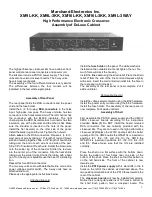
Use jumpers on the 4-position terminal block of the PS10 
power supply to select line voltage, as shown in Figure 6.

220VAC

110VAC

PS10

PS10

Figure 6

Front Panel
DPDT switch

Rear Panel
Fuse Holder

Rear Panel
Power entry

Rear Panel
Voltage selector

GREEN/
YELLOW

N

L

PS10 transformer
terminal block

WHITE

BLACK

WHITE

BLACK

BLACK

BLACK

BROWN

RED

RED

Wire to
case

Figure 7. Power entry with voltage selector switch on rear 
panel and toggle switch on front panel.

Front Panel

DPST rocker switch

Rear Panel
Fuse Holder

Rear Panel
Power entry

Rear Panel
Voltage selector

GREEN/
YELLOW

N

L

PS10 transformer
terminal block

WHITE

BLACK

WHITE

BLACK

BLACK

BLACK

BROWN

RED

RED

Wire to
case

WHITE

Figure 8. Power entry with voltage selector switch on rear 
panel and rocker switch on front panel.

© 2000 Marchand Electronics Inc. PO Box 473, Webster, NY, 14580 www.marchandelec.com (716) 872 0980 FAX: (716) 872 1960

3

Summary of Contents for XM16L-3KK

Page 1: ...hed line cord Please use the appropriate instructions below Attached line cord Install the fuse holder in the panel The white washer is installed on the outward side Gently tighten the nut Too much force will crack the housing Install the line cord using the strain relief Place the strain relief 9 from the end of the line cord and squeeze tightly with pliers Insert the cord and strain relief into ...

Page 2: ... front panel will be attached to the main chassis using 5 black buttonhead screws or flathead screws Figure 3 Sum mode switch cable Putting it all together Prepare 2 4 for 3 way unit cables as shown in Figure 4 The two way unit uses one cable 8 long and another 11 long The 3 way unit has two additional cables 6 long and 15 long Insert all the orange wires from each of the power cables into the ter...

Page 3: ...of the power switch Cut an 8 piece of red high voltage thick insulation hookup wire strip 1 4 at each end and solder to the bottom terminal of the power switch Use 1 2 of heat shrink tubing over this connection as well Secure the free end of the wire in the leftmost terminal of the 4 position terminal block AC input on the PS10 power supply board Cut a 2 piece of brown high voltage hookup wire and...

Page 4: ... should all be set to the center position Connect the 2 4 power cables from the power supply to the crossover boards On the XM9 the cables are plugged into connectors marked P2 On the XM16 the power cables are plugged into the connectors marked P1 The sum mode cable is hooked to two 3 pin molex connectors according to the table 5 The level and damping controls are hooked up according to table 6 Th...

Page 5: ...ard potentiometers should be in the center position Board Location Input Out High Out Low L R L R L R Left Center P6 P7 P8 Right Center P6 P7 P8 Table 1 Connections for RCA input and output connectors XM9L KK Board Location Input Out High Out Low L R L R L R Left Center P5 P6 P7 Right Center P5 P6 P7 Table 2 Connections for RCA input and output connectors XM16L KK 2000 Marchand Electronics Inc PO ...

Page 6: ...put connectors XM16L 3KK Model First Plug Second Plug Board Loc Board Loc XM9L KK L Ctr P5 R Ctr P5 XM9L 3KK Left P5 R Ctr P5 XM16L KK L Ctr P4 R Ctr P4 XM16L 3KK Left P4 R Ctr P4 Table 5 Connections for Sum Mode Cable Model Left Low Left Damping Left High Right Low Right Damping Right High Board Loc Board Loc Board Loc Board Loc Board Loc Board Loc XM9L KK L Ctr P1 L Ctr P3 L Ctr P4 R Ctr P1 R Ct...

Page 7: ...R i g h t Input Hi Out Center Out Low Out Input Hi Out Center Out Low Out 1 2 3 2 4 2 Connections for the front panel controls 1 J 2 5 J 6 3 J 4 Board 1 Board 2 Board 3 Board 4 Installation of jumper blocks as seen from the front panel R5 on board 2 and board 4 should be in the center position ...

Page 8: ...Input Hi Out Low Out 1 Low Damping Hi Input Hi Out Low Out 1 Low Damping Hi Input Hi Out Low Out 1 C e n t e r S u m Sum Out Connections for the front panel controls 1 J 2 5 J 6 3 J 4 Board 1 Board 2 Board 3 Installation of jumper blocks as seen from the front panel ...

Page 9: ...ut Hi Out Center Out Low Out Input Hi Out Center Out Low Out 1 2 3 2 4 2 Connections for the front panel controls 1 J 2 3 J 4 Board 1 Board 2 Board 3 Board 4 Installation of jumper blocks as seen from the front panel R43 on board 2 and board 4 should be in the center position ...

Page 10: ...nk tubing 3 8 diameter 1 1 16 Hex Wrench 1 5 64 Hex Wrench Note 1 Some kits use black flathead swrews instead of buttonhead screws Parts List XM9L 3KK 1 Cabinet front panel XM9 1 Cabinet Rear Panel L 1 Cabinet Top 1 Cabinet Shell 4 Rubber bumper feet 4 6 32x1 2 Panhead Machine Screw 1 Fuse Holder 1 1A Fuse 1 Line Cord 1 Voltage Selector Switch 1 Power Entry Connector 4 RCA connector RED 4 RCA conn...

Page 11: ...ookup wire 1 Grn Yel High Voltage 22 hookup wire 1 1 16 Hex Wrench 1 5 64 Hex Wrench Note 1 Some kits use black buttonhead swrews instead of flathead screws Parts List XM16L 3KK 1 Cabinet front panel XM16 1 Cabinet Rear Panel L 1 Cabinet Shell 1 Cabinet Top 4 Rubber bumper feet 4 6 32x1 2 Panhead Machine Screw 1 Fuse Holder 1 1A Fuse 1 Line Cord 1 Strain relief 4 RCA connector RED 4 RCA connector ...

Page 12: ...4K 1W resistor 1 DPDT Toggle Switch 1 3 pin Female Molex w pins 20 1 2 Threaded Standoff 46 6 32 1 4 Black Panhead Machine Screw 5 6 32 1 2 Black Buttonhead Machine Screw 2 solder lug 2 6 32 Keps Nut 4 4 40 3 8 Machine Screw 4 4 40 Keps Nut 9 Black Aluminum Knob 12 Brown 22 hookup wire 12 Red 22 hookup wire 12 Orange 22 hookup wire 1 Brown High Voltage 22 hookup wire 1 Red High Voltage 22 hookup w...

Reviews: