background image

31

Application

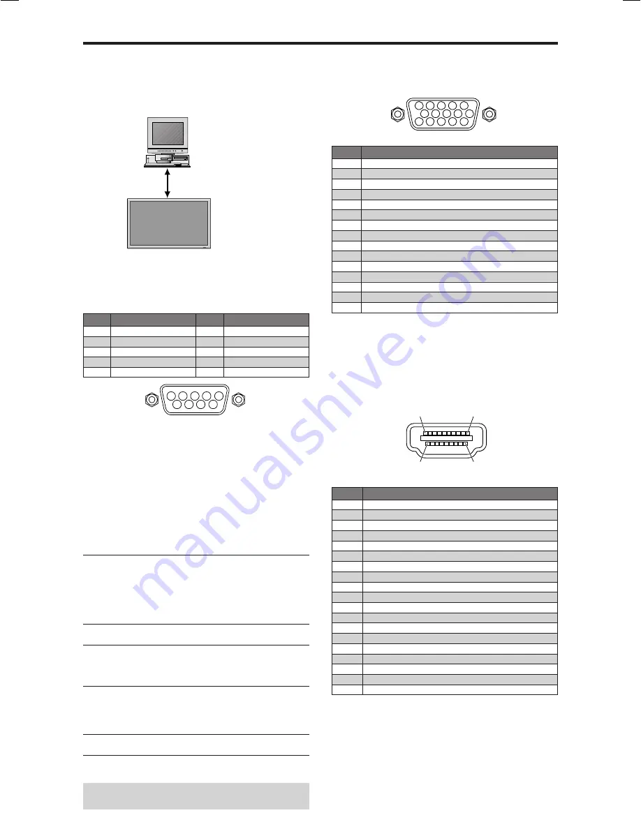
These specifications cover the communications control of
the plasma monitor by external equipment.

Connections

Connections are made as described below.

Connector on the plasma monitor side: EXTERNAL
CONTROL connector.
Use a crossed (reverse) cable.

Type of connector: D-Sub 9-pin male

1

5

9

6

2

3

4

7 8

Communication Parameters

(1) Communication system

Asynchronous

(2) Interface

RS-232C

(3) Baud rate

9600 bps

(4) Data length

8 bits

(5) Parity

Odd

(6) Stop bit

1 bit

(7) Communication code

Hex

External Control Codes (Reference)

FUNCTION

CODE DATA

Power ON

9FH 80H 60H 4EH 00H CDH

OFF

9FH 80H 60H 4FH 00H CEH

Input Switch

Video1 (BNC)

DFH 80H 60H 47H 01H 01H 08H

Video2 (RCA)

DFH 80H 60H 47H 01H 02H 09H

Video3 (S-Video)

DFH 80H 60H 47H 01H 03H 0AH

DVD1/HD1 (RCA)

DFH 80H 60H 47H 01H 05H 0CH

DVD2/HD2 (BNC)

DFH 80H 60H 47H 01H 06H 0DH

DVD3/HD3 (HDMI)

DFH 80H 60H 47H 01H 0EH 15H

RGB1 (mini D-sub 15-pin)

DFH 80H 60H 47H 01H 07H 0EH

RGB2 (5BNC)

DFH 80H 60H 47H 01H 08H 0FH

RGB3 (HDMI)

DFH 80H 60H 47H 01H 0CH 13H

Audio Mute

ON

9FH 80H 60H 3EH 00H BDH

OFF

9FH 80H 60H 3FH 00H BEH

Picture Mode NORMAL

DFH 80H 60H OAH 01H 01H CBH

THEATER 1

DFH 80H 60H OAH 01H 02H CCH

THEATER 2

DFH 80H 60H OAH 01H 03H CDH

DEFAULT

DFH 80H 60H OAH 01H 04H CEH

BRIGHT

DFH 80H 60H OAH 01H 05H CFH

Screen Mode STADIUM

DFH 80H 60H 51H 01H 02H 13H

ZOOM

DFH 80H 60H 51H 01H 03H 14H

NORMAL

DFH 80H 60H 51H 01H 04H 15H

ANAMORPHIC

DFH 80H 60H 51H 01H 05H 16H

14 : 9

DFH 80H 60H 51H 01H 09H 1AH

2.35 : 1

DFH 80H 60H 51H 01H 0AH 1BH

Auto Picture

ON

DFH 80H 60H 7FH 03H 03H 09H 00H 4DH

OFF

DFH 80H 60H 7FH 03H 03H 09H 01H 4EH

Cinema Mode ON

DFH 80H 60H C1H 01H 01H 82H

OFF

DFH 80H 60H C1H 01H 02H 83H

Note: 

Contact your local dealer for a full list of the

External Control Codes if needed.

Display

External equipment
e.g., Personal computer

Pin Name

No Connection
RXD (Receive data)
TXD (Transmit data)
DTR (DTE side ready)
GND

Pin No.

1
2
3
4
5

Pin No.

6
7
8
9

Pin Name

DSR (DCE side ready)
RTS (Ready to send)
CTS (Clear to send)
No connection

External Control

5

4

3

2

1

15 14 13 12 11

10

9

8

7

6

RGB 1 

mini D-Sub 15-pin connector
(Analog)

Signal (Analog)

Red
Green or sync-on-green
Blue
No connection
Ground
Red ground
Green ground
Blue ground
No connection
Sync signal ground
No connection
Bi-directional DATA (SDA)
Horizontal sync or Composite sync
Vertical sync
Data clock

Pin No.

1
2
3
4
5
6
7
8
9

10

11

12
13
14
15

HDMI connector (Digital)

The unit is equipped with a type of connector commonly
used for digital.
(This cannot be used for an analog input.)
(TMDS can be used for one link only.)

No.19

No.18

No.2

No.1

Pin Assignments

Pin No.

1
2
3
4
5
6
7
8
9

10

11

12
13
14
15
16
17
18
19

Signal (Digital)

TMDS Data 2+
TMDS Data 2 Shield
TMDS Data 2-
TMDS Data 1+
TMDS Data 1 Shield
TMDS Data 1-
TMDS Data 0+
TMDS Data 0 Shield
TMDS Data 0-
TMDS Clock+
TMDS Clock Shield
TMDS Clock-
CEC
Reserved (in cable but N.C. on device)
SCL
SDA
DDC/CEC Ground
+5V Power
Hot Plug Detect

06̲Plasma̲31̲40

04.9.2, 11:50 AM

31

Summary of Contents for PD5050D

Page 1: ...Model PD5050D User Guide Plasma Monitor ...

Page 2: ...Electronic Industries Alliance www eiae org 16 Damage Requiring Service The appliance should be serviced by qualified service personnel when A The power supply cord or the plug has been damaged or B Objects have fallen or liquid has been spilled into the appliance or C The appliance has been exposed to rain or D The appliance does not appear to operate normally or exhibits a marked change in perfo...

Page 3: ...nce www eiae org 16 Dommages qu il faut faire réparer Il faut faire réparer l appareil par un technicien qualifié lorsque A Le cordon d alimentation en électricité ou la fiche a été endommagé ou B On a laissé tomber des objets ou du liquide dans l appareil C On a exposé l appareil a la pluie ou D L appareil ne paraît pas marcher normalement ou présente de grands changements d opération ou E On a l...

Page 4: ...occur during shipping or transit or damage which is attributed to acts of God 10 Incidental or consequential damages resulting from the product Some states do not allow the exclusion of incidental or consequential damages so the above ex clusion may not apply to you This warranty gives you specific legal rights and you may also have other rights that vary from state to state 11 Commercial or insti...

Page 5: ... between the equipment and receiver Connect the equipment into an outlet on a circuit different from that to which the receiver is connected Consult the dealer or an experienced radio TV technician for help NOTE When you connect a computer to this monitor use an RGB cable including the ferrite core on both ends of the cable And regarding HDMI and power cable attach the supplied ferrite cores If yo...

Page 6: ...ixation des noyaux en ferrite Monter les tores en ferrite aux deux extrêmités du câble HDMI non fourni et aux deux extrêmités du câble d alimentation électrique fourni Fermez doucement le couvercle jusqu à ce que les crans se clipsent Fixer le tore en ferrite fourni au câble HDMI à l aide d un collier Câble HDMI non fourni Connecteur noyau petit noyau petit Collier Collier noyau grande Câble d ali...

Page 7: ...y the power cord 5 Unplug the power cord during electrical storms or if the unit will not be used over a long period 6 Do not open the cabinet which has potentially dangerous high voltage components inside If the unit is damaged in this way the warranty will be void Moreover there is a serious risk of electric shock 7 Do not attempt to service or repair the unit The manufacturer is not liable for ...

Page 8: ...ble Avoid displaying images with few colors and distinct sharply defined borders between colors Note Burn in is not covered by the warranty Contact your dealer for other recommended procedures that will best suit your particular application needs Mises en garde et précautions de sécurité Ce moniteur à plasma a été conçu et fabriqué pour une utilisation fiable et durable Il ne nécessite aucun entre...

Page 9: ...nt pour le nettoyage de ces surfaces 2 Nettoyer les prises d aération du plasma en procédant à l aide d une brosse à poils doux fixée à un aspirateur 3 Pour garantir la bonne ventilation du moniteur nettoyer les prises d air tous les mois Un nettoyage plus fréquent peut s avérer nécessaire selon les conditions environnantes dans lesquelles le moniteur à plasma est utilisé Pour éviter les risques d...

Page 10: ...e brightness of the room 23 Audio Settings Menu 24 Adjusting the treble bass and left right balance and audio input select 24 Setting the allocation of the audio connectors 24 Image Adjust Settings Menu 24 Adjusting the Position Size Fine Picture PictureADJ 24 SET UP Settings Menu 25 Setting the language for the menus 25 Setting the BNC connectors 25 Checking the signal being transmitted to RGB1 t...

Page 11: ... follow correct mounting procedures could result in damage to the equipment or injury to the installer Product warranty does not cover damage caused by improper installation Use only the mounting kit or stand provided by manufacturer and listed under Options Drawing B Drawing A How to use the safety metal fittings and the screws for safety metal fittings These are fittings for fastening the unit t...

Page 12: ...ries Do not use new and old batteries together or use different types together Do not take apart the batteries heat them or throw them into a fire Operating Range Use the remote control within a distance of about 7 m 23ft from the front of the monitor s remote control sensor and at horizontal and vertical angles of up to approximately 30 The remote control operation may not function if the monitor...

Page 13: ...tons in the On Screen Menu OSM mode Front View MENU ENTER INPUTSELECT DOWN UP LEFT RIGHT EXIT VOLUME MENU ENTER INPUTSELECT DOWN UP LEFT RIGHT EXIT VOLUME 4 5 6 7 1 3 2 t t t t t LEFT and RIGHT Enlarges or reduces the image Functions as the CURSOR buttons in the On Screen Menu OSM mode y y y y y VOLUME DOWN and UP Adjusts the volume Functions as the CURSOR buttons in the On Screen Menu OSM mode u ...

Page 14: ...m the audio menu screen E DVD1 HD1 Connect DVD s High Definition or Laser Discs etc here F DVD2 HD2 RGB2 DVD2 HD2 You can connect DVDs High Definition sources Laser Discs etc here This input can be set for use with an RGB or component source see page 25 RGB2 You can connect an analog RGB signal and the syncronization signal G RGB1 D Sub Connect an analog RGB signal from a computer etc here H DVD3 ...

Page 15: ... i i MUTE Mutes the audio o o o o o VOLUME Adjusts the audio volume 0 0 0 0 0 ZOOM Enlarges or reduces the image 1 1 1 1 1 CONTRAST Press this button to adjust contrast directly 2 2 2 2 2 BRIGHTNESS Press this button to adjust brightness directly 3 3 3 3 3 PICTURE MODE Press this button to adjust picture mode directly 4 4 4 4 4 COLOR TEMP Press this button to adjust color tone directly 5 5 5 5 5 V...

Page 16: ...nu turns off DIGITAL ZOOM Digital zoom specifies the picture position and enlarges the picture 1 Press the ZOOM or button to display magnifying glass To change the size of the picture Press the ZOOM button and enlarge the picture A press of the ZOOM button will reduce the picture and return it to its original size To change the picture position Select the position with the buttons 2 Press the EXIT...

Page 17: ...t ratios Use this for watching normal video programs 4 3 with a wide screen ZOOM size screen The picture is expanded in the horizontal and vertical direction maintaining the original proportions Use this for theater size wide movies etc 2 35 1 size screen The squeezed film image is expanded to fulfill the entire screen at a ratio of 2 35 1 Black bands do not appear at the top and bottom but inform...

Page 18: ... Inc of the United States Note Do not allow the displayed in 4 3 mode for an extended period This can cause a phosphor burn in Wide Screen Operation with Computer Signals Switch to the wide screen mode to expand the 4 3 image to fill the entire screen 1 Press the WIDE button on the remote control 2 Within 3 seconds Press the WIDE button again The screen size switches as follows NORMAL ANAMORPHIC Z...

Page 19: ...INT NR COLOR TEMP GAMMA LOW TONE SET UP LEVEL COLOR TUNE CINEMA MODE PICTURE MODE OFF OFF MIDDLE 2 2 AUTO 0 ON NORMAL G R 4 Adjust the level or change the setting of the selected item by using the cursor buttons on the remote control CONTRAST 10 5 The adjustments or the settings that are stored in memory The change is stored until you change it again 6 Repeat steps 2 5 to adjust an additional item...

Page 20: ...1 3 RGB 1 3 YES 24 AUDIO INPUT2 VIDEO 1 3 HD DVD 1 3 RGB 1 3 YES 24 AUDIO INPUT3 VIDEO 1 3 HD DVD 1 3 RGB 1 3 YES 24 Main menu Sub menu Sub menu 2 Sub menu 3 Sub menu 4 RESET REFERENCE IMAGE ADJUST ASPECT MODE ZOOM NORMAL ANAMORPHIC STADIUM 14 9 2 35 1 NO 24 V POSITION 64 0 64 YES 24 H POSITION 128 0 127 YES 24 V HEIGHT 0 64 YES 24 H WIDTH 0 64 YES 24 AUTO PICTURE ON OFF 2 NO 24 FINE PICTURE 1 2 0...

Page 21: ...NVERSE WHITE OFF INVERSE WHITE YES 29 SCREEN WIPER ON OFF YES 29 SOFT FOCUS OFF LEVEL1 4 YES 29 OSM ORBITER ON OFF YES 30 OSM CONTRAST LOW NORMAL YES 30 CLOSED CAPTION OFF CAPTION1 4 TEXT1 4 YES 30 CAPTION CONT LOW NORMAL YES 30 Main menu Sub menu Sub menu 2 Sub menu 3 Sub menu 4 RESET REFERENCE SIGNAL INFO 30 Information Restoring the factory default settings Select ALL RESET under the SET UP men...

Page 22: ...ve finished inputting the note press the MENU ENTER button Adjusting the picture The contrast brightness sharpness color and tint can be adjusted as desired Example Adjusting the contrast On CONTRAST of PICTURE menu adjust the contrast SEL ADJ EXIT RETURN PICTURE PICTURE MEMORY CONTRAST BRIGHTNESS SHARPNESS COLOR TINT NR COLOR TEMP GAMMA LOW TONE SET UP LEVEL COLOR TUNE CINEMA MODE PICTURE MODE OF...

Page 23: ...ings to the factory default values Use and buttons to select ON then press the MENU ENTER button Restoring the factory default settings Select RESET under the WHITE BALANCE menu Changing the Gamma Curve This feature adjusts the brightness of the midtone areas while keeping shadows and highlights unchanged Example Setting 2 3 On GAMMA of PICTURE menu select 2 3 SEL ADJ EXIT RETURN PICTURE PICTURE M...

Page 24: ...y discriminated and projected in an image mode suited to the picture NTSC PAL PAL60 480I 60Hz 525I 60Hz 576I 50Hz 625I 50Hz 1035I 60Hz 1080I 60Hz only Example Setting the CINEMA MODE to OFF On CINEMA MODE of PICTURE menu select OFF SEL ADJ EXIT RETURN PICTURE PICTURE MEMORY CONTRAST BRIGHTNESS SHARPNESS COLOR TINT NR COLOR TEMP GAMMA LOW TONE SET UP LEVEL COLOR TUNE CINEMA MODE PICTURE MODE OFF OF...

Page 25: ... as follows each time the 䊴 or 䊳 button is pressed NORMAL ANAMORPHIC The mode can also be switched by pressing the WIDE button on the remote control The settings on the IMAGEADJUST menu are not preset at the factory SEL ADJ EXIT RETURN IMAGE ADJUST ASPECT MODE V POSITION H POSITION V HEIGHT H WIDTH AUTO PICTURE FINE PICTURE PICTURE ADJ NORMAL OFF V POSITION 30 Information 䡵 When AUTO PICTURE is OF...

Page 26: ...be adjusted SET UP LANGUAGE BNC INPUT D SUB INPUT HD SELECT RGB SELECT HDMI SET UP COLOR SYSTEM BACK GROUND GRAY LEVEL S1 S2 DISPLAY OSM OSM ADJ ALL RESET ENGLISH COMPONENT RGB 1080I PC AUTO AUTO GRAY 3 OFF ON TOP LEFT OFF CAN NOT ADJUST Setting high definition images to the suitable screen size Use this procedure to set whether the number of vertical lines of the input high definition image is 10...

Page 27: ...set to HIGH automatically 䡵 BLACK LEVEL settings LOW When connected to the PC signal HIGH When connected to the SET TOP BOX DVD etc Change HIGH into LOW if the black level appears gray Setting the video signal format Use these operations to set the color systems of composite video signals or Y C input signals Example Setting the color system to 3 58 NTSC On COLOR SYSTEM of SET UP menu select 3 58N...

Page 28: ...yed even if you press the MENU ENTER button Example Turning the DISPLAY OSM off On DISPLAY OSM of SET UP menu select OFF SEL ADJ EXIT RETURN SET UP LANGUAGE BNC INPUT D SUB INPUT HD SELECT RGB SELECT HDMI SET UP COLOR SYSTEM BACK GROUND GRAY LEVEL S1 S2 DISPLAY OSM OSM ADJ ALL RESET ENGLISH COMPONENT RGB 1080I PC AUTO AUTO GRAY 3 OFF OFF TOP LEFT OFF Setting the position of the menu Adjusts the po...

Page 29: ... the picture back on Picture already on Operate the keyboard or mouse The picture reappears POWER STANDBY indicator Green Red Power management operating status Not activated Activated Description Horizontal and vertical synchronizing signals are present from the computer Horizontal and or vertical synchronizing signals are not sent from the computer Setting the Input Skip When this is ON signals w...

Page 30: ...ture and will not make the screen smaller or bigger INVERSE WHITE Use this to set the inverse mode or to display a white screen Example Setting INVERSE WHITE to WHITE On INVERSE WHITE of PDP SAVER menu select WHITE SEL ADJ EXIT RETURN PDP SAVER PEAK BRIGHT ORBITER INVERSE WHITE SCREEN WIPER SOFT FOCUS OSM ORBITER OSM CONTRAST 100 OFF WHITE OFF OFF ON LOW Information 䡵 INVERSE WHITE Settings OFF In...

Page 31: ...n Use this to reduce the brightness of Closed Caption Example Setting NORMAL On CAPTION CONT of FUNCTION menu select NORMAL SEL ADJ EXIT RETURN FUNCTION POWER MGT INPUT SKIP PDP SAVER CLOSED CAPTION CAPTION CONT OFF OFF MANUAL OFF NORMAL Information 䡵 CAPTION CONT settings NORMAL Closed Caption brightness is set to normal LOW Closed Caption brightness is set to lower Signal Information Menu Checki...

Page 32: ...L DFH 80H 60H 51H 01H 04H 15H ANAMORPHIC DFH 80H 60H 51H 01H 05H 16H 14 9 DFH 80H 60H 51H 01H 09H 1AH 2 35 1 DFH 80H 60H 51H 01H 0AH 1BH Auto Picture ON DFH 80H 60H 7FH 03H 03H 09H 00H 4DH OFF DFH 80H 60H 7FH 03H 03H 09H 01H 4EH Cinema Mode ON DFH 80H 60H C1H 01H 01H 82H OFF DFH 80H 60H C1H 01H 02H 83H Note Contact your local dealer for a full list of the External Control Codes if needed Display E...

Page 33: ...een Part of picture is cut off or picture is not centered Image is too large or too small Picture is unstable POWER STANDBY indicator is lighted in red POWER STANDBY indicator is blinking in red POWER STANDBY indicator is blinking in green and red or green Checks Are the image and sound normal Is a connected component set directly in front or at the side of the display Are the remote control s bat...

Page 34: ...AY OSM OSM ADJ ALL RESET FUNCTION POWER MGT INPUT SKIP SUB P DETECT ZOOM NAV PICTURE FREEZE PDP SAVER PEAK BRIGHT ORBITER INVERSE WHITE SCREENWIPER SOFT FOCUS OSM ORBITER OSM CONTRAST CLOSED CAPTION CAPTION CONT SIGNAL INFO The features and specifications may be subject to change without notice 1 HD DVD DTV input signals supported on this system 480P 60 Hz 480I 60 Hz 525P 60 Hz 525I 60 Hz 576P 50 ...

Page 35: ... YES YES YES YES YES YES YES YES YES YES YES YES YES YES YES YES YES YES YES YES YES YES YES 3 YES 3 YES YES YES YES YES YES YES YES YES YES YES YES YES YES YES YES YES YES YES YES YES YES YES YES YES YES YES 7 YES 7 RGB select 5 STILL STILL WIDE2 WIDE1 STILL STILL STILL STILL STILL WIDE1 WIDE3 WIDE1 WIDE1 WIDE2 WIDE1 WIDE1 WIDE2 STILL WIDE4 WIDE2 WIDE3 WIDE1 WIDE1 MOTION Apple Macintosh 6 8 Horiz...

Page 36: ...o Macintosh computer use the monitor adapter D Sub 15 pin to your computer s video port 7 Other screen modes ZOOM and STADIUM are available as well 8 When viewing a moving picture at a vertical frequency greater than 65Hz the picture may sometimes be unstable jumpy If this occurs please set the refresh rate of the external equipment to 60Hz To view 480I 60Hz 480 interlaced lines 60Hz refresh rate ...

Page 37: ... find your nearest authorized distributor or dealer on our website JAPAN Marantz Japan Inc 35 1 Sagami Ohno 7 Chome Sagamihara shi Kanagawa 228 8505 Japan U S A Marantz America Inc 1100 Maplewood Drive Itasca IL 60143 U S A EUROPE Marantz Europe B V P O Box 8744 5605 LS Eindhoven The Netherlands ...

Reviews: