


34
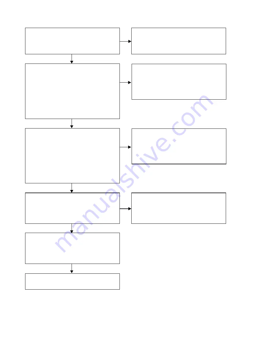
3.1. Optical Output
Check the Power Supply Voltages for Optical.
MAIN PCB
・
+3.3V_D1
[JACK106
、
2pin]
Check the status of the following parts and check the solder.
MAIN PCB
L153, IC125
Other, connected circuit.
NO
YES
Check the DIR clock.
MAIN PCB
・
The clock signal of 24.576MHz will be output.
[IC113
、
40in]
Check the status of the following parts and check the solder.
FRONT PCB
IC113, X102
Other, connected circuit.
NO
See "3.3. Check the Audio Block"
YES
Check the audio data for DIR.
MAIN PCB
There are no abnormal voltages, such as middle potential.
There is no abnormal waveform.
CY920_PBCK_DBCK [IC113
、30
pin]
CY920_LRCK
[IC113
、29
pin]
CY920_PDATA_DSDL [IC113
、28
pin]
Signal of R472
[IC113
、31
pin]
Check the status of the following parts and check the solder.
MAIN PCB
IC113, CN101, CN102(
CY920MODULE)
Other, connected circuit.
NO
YES
Check the control signal for DIR.
MAIN PCB
There are no abnormal voltages, such as middle potential.
There is no abnormal waveform.
DIR_RST [IC113
、
34pin]
DIR_DAI [IC113
、
24pin]
DIR_CLK [IC113
、
25pin]
DIR_CS
[IC113
、
26pin]
DIR_DAO [IC113
、
23pin]
Check the status of the following parts and check the solder.
FRONT PCB
IC113,IC101
Other, connected circuit.
NO
YES
Check the status of the following parts and check the solder.
FRONT PCB
IC113
Other, connected circuit.
YES
Summary of Contents for NA6005
Page 8: ...Personal notes 8 ...
Page 30: ...Personal notes 30 ...
Page 39: ...BLOCK DIAGRAM 39 ...
Page 40: ...POWER DIAGRAM 40 ...


