4. SERVICE MODE
1. How to enter into the Service Mode
Turn the power on while pressing [PLAY]+[OPEN/
CLOSE] buttons together.
The display shows “model number”, “microprocessor ver-
sion” and “mode”.
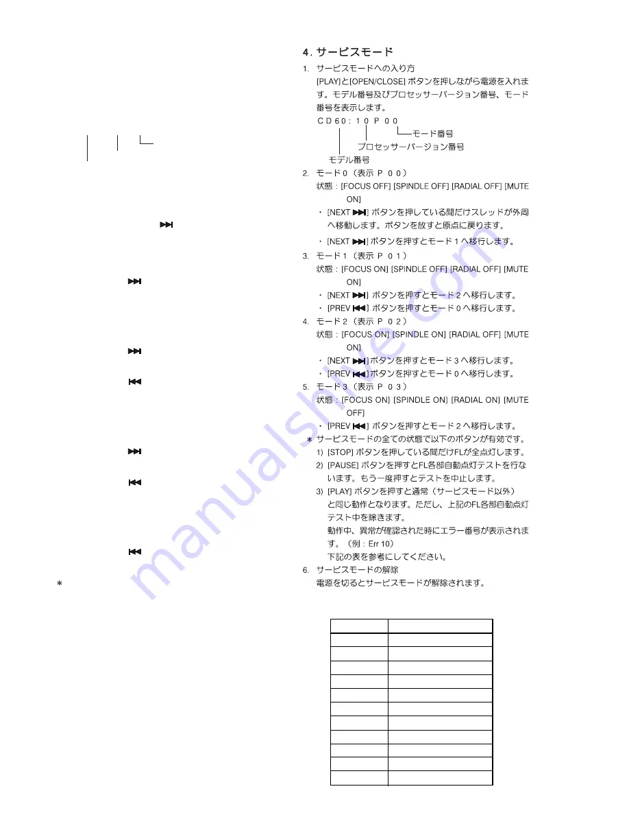
C D 6 0 : 1 0 P 0 0
Mode number
Microprocessor version
Model number
2. Mode 0 (display “P 00”)
Condition: [FOCUS OFF], [SPINDLE OFF], [RADIAL
OFF], [MUTE ON]
•
While pressing [NEXT
] button,the sledge moves out
side.
And, release from this button. The sledge return to
neutral position.
•
Press [NEXT
] button, the function will change to
“Mode 1”.
3. Mode 1 (display “P 01”)
Condition: [FOCUS ON], [SPINDLE OFF], [RADIAL OFF],
[MUTE ON]
•
Press [NEXT
] button, the function will change to
“Mode 2”.
•
Press [PREV
] button, the function will change to
“Mode 0”.
4. Mode 2 (display “P 02”)
Condition: [FOCUS ON], [SPINDLE ON], [RADIAL OFF],
[MUTE ON]
•
Press [NEXT
] button, the function will change to
“Mode 3”.
•
Press [PREV
] button, the function will change to
“Mode 1”.
5. Mode 3 (display “P 03”)
Condition: [FOCUS ON], [SPINDLE ON], [RADIAL ON],
[MUTE OFF]
•
Press [PREV
] button, the function will change to
“Mode 2”.
The following button operations are available at the
Service Mode.
1) While pressing [STOP] button, FL display shows all
segments.
2) Press [PAUSE] button. FL display shows each
segments one by one automatically. (Segments test
mode) And, press [PAUSE] button again, this mode will
be stopped.
3) The same as Normal operation is performed by
pressing [PLAY] button. (Except segments test mode.)
However if some default is detected, display shows an
error code. (For example: “Err 10”) Refer to the “Table
1 ERROR CODE”.
6. Canceling the Service Mode
The Service Mode is canceled by turning the power off.
Error Code
Error
Err 02
FOCUS Error
Err 07
SUB CODE Error
Err 08
T. O. C. Error
Err 09
DECODER Error
Err 10
RADIAL Error
Err 11, 12
SLEDGE Error
Err 13
SPINDLE Error
Err 16 ~ 20
SEARCH Error
Err 30
DOOR Error
Err 31
TRAY Error
Err 32 ~ 47
BUTTON INPUT Error
Table 1 ERROR CODE
4
Summary of Contents for CD6000 series
Page 11: ...13 14 AUDIO AMPLIFIER PCB COMPONENT SIDE VIEW...
Page 12: ...15 16 AUDIO AMPLIFIER PCB COPPER SIDE VIEW...
Page 15: ...21 CONTROL PCB COMPONENT SIDE VIEW...
Page 16: ...22 HDAM PCB COMPONENT SIDE VIEW...
Page 21: ...31 32...


