3. Route the communication cable to the PLC/host. Refer to the “OIT Cable
Routing” section for more information.
4. Connect the other end of the cable to the PLC/host and tighten the cable screws.
5. Connect the green shield wire from the cable to earth ground (chassis
ground) on the PLC. If this wire is not present, the ground connection was
made inside the connector.
1010-0104, REV 03
14
OIT3185A/4185A
PIN#
FUNCTION
1
TXD+
2
TXD-
3
CTS
4
RETURN
5
TXD
6
RXD
7
RXD-
8
RXD+
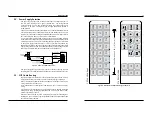
Figure 6 Port 1 Pin Outs
3.4. Mount OIT to Panel
STEPS
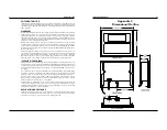
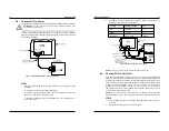
1. Gently position the OIT with the studs through the panel mounting holes.
2. Secure the OIT by installing the four #6-32UNC mounting nuts using a 5/16
inch socket wrench or nut driver.
CAUTION:
Do not torque the 4 mounting nuts to over 15 pound-inches. Over
torquing can strip the threads or pull the studs loose.
RE-INSTALLING:
Because the gasket will take a “set” to the panel, be sure to
re-install any OIT to the same panel cutout when a NEMA 4/12 seal is required.
1010-0104, REV 03
INSTALLATION MANUAL
11
Figure 3 OIT3185/4185 Panel Mounting


