background image


16 


Montage- und Betriebsanleitung 

Installation and Operating Instructions


EN 

44..22


TToooollss  aanndd  m

maatteerriiaallss  rreeqquuiirreedd  


TORX®-screw driver IP15 


TORX® torque wrench IP15 


Protective gloves 


Compressed air blow gun 

55


CChhaannggiinngg  tthhee  iinnddeexxaabbllee  iinnsseerrttss  


CCAAU

UTTIIO

ON

N


SShhaarrpp  ccuuttttiinngg  eeddggeess  oonn  tthhee  ttooooll!!  
Sharp cutting edges may cause cutting injuries. 

 Wear protective gloves when changing inserts. 


Clean the tool before beginning to 
change the inserts. 


Release the clamping screw with the 
suitable TORX®-screw driver, to do this 
rotate the screw anti-clockwise. 


Remove the clamping screw. 

Fig. 2:


Releasing the clamping screw 


Carefully slide the insert up the insert 
pocket and remove the insert. 


IIN

NFFO

ORRM

MAATTIIO

ON

N


When exchanging an insert all in-
serts must be exchanged! 


Remove the remaining inserts. 

Fig. 3:


Removing the insert 


Montage- und Betriebsanleitung 

Installation and Operating Instructions

17 

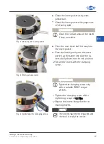
Clean the insert pocket using com-
pressed air. 
Clean the insert pocket with proper use 
of cleaning spirit. 

IIN

NFFO

ORRM

MAATTIIO

ON

N


Clean the contact areas of the insert 
if they are soiled. 

Fig. 4:


Cleaning the insert pocket 

Place the new insert half the way into 
the insert pocket. 
Press the insert gently into the insert 
pocket, at the same time slide the in-
sert axially down into the end position. 


Secure the insert with the clamping 
screw. 

Fig. 5:


Fitting a new insert 

IIN

NFFO

ORRM

MAATTIIO

ON

N


Tighten the clamping screw only 
with a suitable TORX® torque 
wrench. 


Tighten the clamping screw with a 
tightening torque of 33,,11  N

Nm

m. 


Repeat the insert change for the re-
maining inserts. 

RREESSU

ULLTT


The inserts have been replaced and 
the tool is ready for service.


Fig. 6:


Tightening the clamping screw 

Montage- und Betriebsanleitung

Installation and Operating Instructions

16

EN

Summary of Contents for HPR400

Page 1: ...tung Installation and Operating Instructions Hochleistungsreibahle HPR400 High Performance Reamer HPR400 D E Montage und Betriebsanleitung Installation and Operating Instructions Hochleistungsreibahle HPR400 High Performance Reamer HPR400 ...

Page 2: ...E ...

Page 3: ...w wä äh hr rl le ei is st tu un ng g 6 6 3 3 5 5 A Al ll lg ge em me ei in ne e W Wa ar rn n u un nd d S Si ic ch he er rh he ei it ts sh hi in nw we ei is se e 6 6 4 4 A Al ll lg ge em me ei in ne e I In nf fo or rm ma at ti io on ne en n 7 7 4 4 1 1 D Da ar rs st te el ll lu un ng g e ei in ne es s H HP PR R4 40 00 0 7 7 4 4 2 2 B Be en nö öt ti ig gt te e W We er rk kz ze eu ug ge e H Hi il lf ...

Page 4: ...etriebsanleitung ist Bestandteil der Hochleistungsreibahle und muss in unmittelbarer Nähe und für das Personal jederzeit zugänglich aufbe wahrt werden Grundvoraussetzung für sicheres Arbeiten ist die Einhaltung aller angegebenen Sicherheitshinweise und Handlungsanweisungen in dieser Mon tage und Betriebsanleitung Darüber hinaus gelten die örtlichen Arbeitsschutzvorschriften und allgemeinen Sicherh...

Page 5: ...und ihre Komponenten darf nur verwendet werden wenn die Einhaltung aller Angaben dieser Betriebsanleitung gewähr leistet ist Falls auf dem Werkzeug eine maximale Betriebsdrehzahl vorhanden ist darf diese nicht überschritten werden Das Abweichen der Vorschriften kann zu Verletzungen oder Beschädigungen von Maschinen und Zubehör führen für die MAPAL keine Haftung über nimmt 3 3 3 3 N Ni ic ch ht t b...

Page 6: ... us sg ge eb bi il ld de et te es s u un nd d u un na au ut to or ri is si ie er rt te es s P Pe er rs so on na al l Das Spannen von Werkzeugen und Einbringen in eine Werkzeugmaschine kann durch unausgebildetes und unautorisiertes Personal zu gefährlichen Situationen führen Ausschließlich ausgebildetes autorisiertes und zuverlässiges Fachpersonal darf Werkzeuge spannen und in eine Werkzeugmaschine...

Page 7: ... erhöhten Verschleiß des Spannsatzes Die Spannschraube nur manuell spannen I IN NF FO OR RM MA AT TI IO ON N Das Wechseln der Schneidplatten darf nur von geschultem Personal durch geführt werden 4 4 A Al ll lg ge em me ei in ne e I In nf fo or rm ma at ti io on ne en n 4 4 1 1 D Da ar rs st te el ll lu un ng g e ei in ne er r H Ho oc ch hl le ei is st tu un ng gs sr re ei ib ba ah hl le e H HP PR ...

Page 8: ...n verursachen Beim Schneidplattenwechselwechsel Schutzhandschuhe tragen Reinigen Sie das Werkzeug vor Beginn des Schneidplattenwechsels Lösen Sie die Spannschraube indem Sie mit einem passenden TORX Schrau bendreher die Spannschraube gegen den Uhrzeigersinn drehen Entnehmen Sie die Spannschraube Abb 2 Spannschraube lösen Schieben Sie die Schneidplatte in axia ler Richtung vorsichtig aus dem Schnei...

Page 9: ...nd schieben Sie die Schneidplatte gleich zeitig axial nach unten in die Endposi tion Fixieren Sie die Schneidplatte mit der Spannschraube um das Herausfallen der Schneidplatte zu verhindern Abb 5 Neue Schneidplatte einsetzen I IN NF FO OR RM MA AT TI IO ON N Die Spannschraube nur mit einem passenden TORX Drehmoment schlüssel anziehen Ziehen Sie die Spannschraube mit ei nem Anzugsdrehmoment von 3 3...

Page 10: ...Reparaturen dürfen ausschließlich im Hause MAPAL durchgeführt werden 7 7 E En nt ts so or rg gu un ng g Nachdem das Gebrauchsende der Hochleistungsreibahle HPR400 erreicht ist muss sie einer umweltgerechten Entsorgung zugeführt werden Die Hochleis tungsreibahle HPR400 kann zur fachgerechten Entsorgung auch an MAPAL ge sendet werden DE Montage und Betriebsanleitung Installation and Operating Instru...

Page 11: ... 13 3 3 3 4 4 W Wa ar rr ra an nt ty y 1 14 4 3 3 5 5 G Ge en ne er ra al l w wa ar rn ni in ng gs s a an nd d s sa af fe et ty y i in ns st tr ru uc ct ti io on ns s 1 14 4 4 4 G Ge en ne er ra al l i in nf fo or rm ma at ti io on n 1 15 5 4 4 1 1 I Il ll lu us st tr ra at ti io on n o of f a a H HP PR R4 40 00 0 1 15 5 4 4 2 2 T To oo ol ls s a an nd d m ma at te er ri ia al ls s r re eq qu ui i...

Page 12: ...ctions form an integral part of the high per formance reamer and must be kept in the immediate vicinity and be accessible to personnel at all times A basic precondition for safe working is compliance with all the safety precautions and instructions for working given in these installation and operating instructions The local safety at work regulations and the general safety regulations for the fiel...

Page 13: ... its components may only be used when observance of all the instructions given in these operating instructions is assured If there is a maximum operating speed indicated on the tool it must not be exceeded Failure to observe these instruction can result in injuries or damage to ma chines and accessories for which MAPAL assumes no liability 3 3 3 3 I In nc co or rr re ec ct t u us se e The tool or ...

Page 14: ...g ge er r f fr ro om m u us se e b by y u un nt tr ra ai in ne ed d a an nd d u un na au ut th ho or ri is se ed d p pe er rs so on nn ne el l The clamping of tools and their installation on a machine tool by untrained and unauthorised personnel can lead to hazardous situations Only trained authorised and dependable specialist personnel may clamp tools and install them on a machine tool The techni...

Page 15: ...t in in creased wear of the clamping set Tighten the clamping screw only manually I IN NF FO OR RM MA AT TI IO ON N Only trained personnel are permitted to change the inserts 4 4 G Ge en ne er ra al l i in nf fo or rm ma at ti io on n 4 4 1 1 I Il ll lu us st tr ra at ti io on n o of f a a h hi ig gh h p pe er rf fo or rm ma an nc ce e r re ea am me er r H HP PR R4 40 00 0 L Le eg ge en nd d 1 Ins...

Page 16: ... th he e t to oo ol l Sharp cutting edges may cause cutting injuries Wear protective gloves when changing inserts Clean the tool before beginning to change the inserts Release the clamping screw with the suitable TORX screw driver to do this rotate the screw anti clockwise Remove the clamping screw Fig 2 Releasing the clamping screw Carefully slide the insert up the insert pocket and remove the in...

Page 17: ...y into the insert pocket at the same time slide the in sert axially down into the end position Secure the insert with the clamping screw Fig 5 Fitting a new insert I IN NF FO OR RM MA AT TI IO ON N Tighten the clamping screw only with a suitable TORX torque wrench Tighten the clamping screw with a tightening torque of 3 3 1 1 N Nm m Repeat the insert change for the re maining inserts R RE ES SU UL...

Page 18: ...osion when stored Repairs must only be performed at MAPAL 7 7 D Di is sp po os sa al l Once the high performance reamer HPR400 reaches the end of its service life it must be disposed of with due care for the protection of the environment The high performance reamer HPR400 can also be sent to MAPAL for proper disposal Montage und Betriebsanleitung Installation and Operating Instructions 18 EN ...

Page 19: ......

Page 20: ...s KG Aalen reproduziert oder unter Verwendung elektronischer Systeme verarbeitet werden No part of this manual is allowed to be copied or processed using electronic systems in any form print photocopy microfilm or any other method without the written approval of MAPAL Präzisionswerkzeuge Dr Kress KG Aalen Germany Alle in diesem Handbuch genannten Bezeichnungen von Erzeugnissen sind Warenzeichen de...

Reviews: