background image

Section 7

Refrigeration System

 Part Number 80-1559-3

7-9

Safety Limit #1

Refer to previous page for safety limit operation.

Freeze time exceeds 60 minutes for 6 consecutive freeze cycles

.

SAFETY LIMIT NOTES

Because there are many possible external problems, 
do not limit your diagnosis to only the items listed in 
this chart.

A continuous run of 100 harvests automatically 
erases the safety limit code.

The control board will store and indicate only one 
safety limit – the last one exceeded.

If the toggle switch is moved to the OFF position and 
then back to the ICE position prior to reaching the 
100-harvest point, the last safety limit exceeded will 
be indicated.

If a Safety Limit light did not flash prior to the ice 
machine restarting, then the ice machine did not stop 
because it exceeded a safety limit.

Possible Cause

Check/Correct

Improper installation

See “Installation/Visual Inspection Checklist”

Water system

Low water pressure [20 psi (138 kPa) min.]
High water pressure [80 psi (552 kPa) max.]
High water temperature (90°F/32.2°C max.)
Clogged water distribution tube
Dirty/defective water fill valve
Dirty/defective water dump valve
Defective water pump
Loss of water from sump area

Electrical system

Low incoming voltage
Ice thickness probe out of adjustment
Harvest cycle not initiated electrically
Contactor not energizing
Compressor electrically non-operational
Defective fan cycling control
Defective fan motor

Miscellaneous

Restricted condenser airflow
High inlet air temperature (Self-Contained -110°F/43.3°C max.)
Restricted condenser water flow
Low water pressure [20 psi (138 kPa) min.]
High water temperature (90°F/32.2°C max.)
Dirty/defective water regulating valve
Water regulating valve out of adjustment

Refrigeration system

Improper refrigerant charge
Non-Manitowoc components
Defective head pressure control (remotes)
Defective harvest valve
Defective compressor
TXV starving or flooding (check bulb mounting)
Non-condensables in refrigeration system
Plugged or restricted high side refrigerant lines or component

Summary of Contents for S1000M

Page 1: ...ader in ice making equipment and related products With proper installation care and maintenance your new Manitowoc Ice Machine will provide you with many years of reliable and economical performance S Model S1000M Ice Machines Service Manual Part Number 80 1559 3 5 2005 ...

Page 2: ... original manufactured specifications Warning Text in a Warning box alerts you to a potential personal injury situation Be sure to read the Warning statement before proceeding and work carefully Caution Text in a Caution box alerts you to a situation in which you could damage the ice machine Be sure to read the Caution statement before proceeding and work carefully Important Text in an Important b...

Page 3: ...uctions General 2 1 Ice Machine Dimensions 2 1 s1000M Ice Machines 2 1 Location of Ice Machine 2 2 Ice Machine Heat of Rejection 2 2 Electrical Service 2 3 General 2 3 Voltage 2 3 Fuse Circuit Breaker 2 3 Minimum Circuit Ampacity 2 3 Electrical Requirements 2 3 Self Contained Electrical Wiring Connections 2 4 Self Contained Ice Machine 115 1 60 or 208 230 1 60 2 4 Self Contained Ice Machine 208 23...

Page 4: ...ce Machine Inspection 4 1 Exterior Cleaning 4 1 Water Cooled Condenser and Water Regulating Valve 4 1 AlphaSan 4 1 Guardian 4 2 Guardian Sachet Replacement Frequency 4 2 Sachet Replacement Procedure 4 2 Clean Up Procedure for Damaged Sachet Packet 4 2 Interior Cleaning and Sanitizing 4 3 General 4 3 Cleaning Procedure 4 3 Sanitizing Procedure 4 4 Removal of Parts For Cleaning Sanitizing 4 5 Removi...

Page 5: ...evel Control Circuitry 6 24 Water Level Probe Light 6 24 Water Inlet Valve Safety Shut Off 6 24 Freeze Cycle Circuitry 6 24 Harvest Cycle Circuitry 6 24 Diagnosing Water Level Control Circuitry 6 25 Diagnosing An Ice Machine That Will Not Run 6 27 Section 7 Refrigeration System Sequence of Operation 7 1 Self Contained Water Cooled Models 7 1 Operational Analysis Diagnostics 7 3 General 7 3 Before ...

Page 6: ... Evacuation and Recharging 7 20 Normal Self Contained Model Procedures 7 20 System Contamination Clean Up 7 23 Replacing Pressure Controls Without Removing Refrigerant Charge 7 25 Filter Driers 7 27 Total System Refrigerant Charges 7 27 Refrigerant Definitions 7 28 Refrigerant Re Use Policy 7 29 HFC Refrigerant Questions and Answers 7 30 ...

Page 7: ...o not operate equipment that has been misused abused neglected damaged or altered modified from that of original manufactured specifications Warning PERSONAL INJURY POTENTIAL Remove all ice machine panels before lifting and installing Dice 7 8 x 7 8 x 7 8 2 22 x 2 22 x 2 22 cm Half Dice 3 8 x 1 1 8 x 7 8 0 95 x 2 86 x 2 22 cm S Y 1005 W M ICE MACHINE MODEL ICE CUBE SIZE D DICE Y HALF DICE CUBE SIZ...

Page 8: ...affordable method of inhibiting scale formation filtering sediment and removing chlorine taste and odor MANITOWOC CLEANER AND SANITIZER Manitowoc Ice Machine Cleaner and Sanitizer are available in convenient 16 oz 473 ml bottles These are the only cleaner and sanitizer approved for use with Manitowoc products AUCS AUTOMATIC CLEANING SYSTEM This accessory reduces equipment cleaning expense The AuCS...

Page 9: ...s are required when requesting information from your local Manitowoc distributor or Manitowoc Ice Inc The model and serial number are listed on the MODEL SERIAL NUMBER DECAL affixed to the ice machine remote condenser and storage bin Model Serial Number Location SV13147 MODEL SERIAL PLATE LOCATION ...

Page 10: ...m Manitowoc Ice Inc 3 Damage caused by improper installation of the ice machine electrical supply water supply or drainage or damage caused by floods storms or other acts of God 4 Premium labor rates due to holidays overtime etc travel time flat rate service call charges mileage and miscellaneous tools and material charges not listed on the payment schedule Additional labor charges resulting from ...

Page 11: ...HINES Important Failure to follow these installation guidelines may affect warranty coverage ELECTRICAL DRAIN 1 2 NPTF WATER INLET 3 8 FPT CONDENSER WATER OUTLET 1 2 FPT CONDENSER WATER INLET 3 8 FPT AUXILLARY BASE DRAIN 1 2 CPVC SOCKET 2 20 5 58cm H D W 25 52 64 82cm 8 49 21 56cm 6 68 16 96cm 5 06 12 85cm 1 06 2 69cm 2 85 7 30cm 4 21 10 69cm 1 81 4 59cm 2 61 6 62cm A B WATER COOLED SV3143 SV3143B...

Page 12: ... information is also necessary when evaluating the benefits of using water cooled or remote condensers to reduce air conditioning loads The amount of heat added to an air conditioned environment by an ice machine using a water cooled or remote condenser is negligible Knowing the amount of heat rejected is also important when sizing a cooling tower for a water cooled condenser Use the peak figure f...

Page 13: ...e is also dependent upon location materials used length of run etc so it must be determined by a qualified electrician ELECTRICAL REQUIREMENTS Refer to Ice Machine Model Serial Plate for voltage amperage specifications S Series Ice Machines Warning All wiring must conform to local state and national codes Warning The ice machine must be grounded in accordance with national and local electrical cod...

Page 14: ... GROUND ICE MACHINE CONNECTIONS SV1258 TO SEPARATE FUSE BREAKER L1 L1 GROUND GROUND ICE MACHINE CONNECTIONS TO SEPARATE FUSE BREAKER L2 L3 L2 L3 SV1190 L1 L1 N N GROUND GROUND ICE MACHINE CONNECTIONS TO SEPARATE FUSE BREAKER DISCONNECT ALL POLES SV1191 For United Kingdom Only As the colors of the wires in the mains lead of the appliance may not correspond with the colored markings identifying the ...

Page 15: ...enough to accommodate drainage from all drains Run separate bin and ice machine drain lines Insulate them to prevent condensation Vent the bin and ice machine drain to the atmosphere Do not vent the condenser drain on water cooled models Cooling Tower Applications Water Cooled Models A water cooling tower installation does not require modification of the ice machine The water regulator valve for t...

Page 16: ...nser Water Inlet 40 F 4 4 C Min 90 F 32 2 C Max 20 psi 137 9 kPA Min 150 psi 1034 2 kPA Max 3 8 Female Pipe Thread Condenser Water Drain 1 2 Female Pipe Thread 1 2 1 27 cm minimum inside diameter Bin Drain 3 4 Female Pipe Thread 3 4 1 91 cm minimum inside diameter SV3142 ELECTRICAL ENTRANCE 18 46 CM VENT TUBE AIR GAP 1 2 1 3 CM MIN DRAIN ID 1 2 DRAIN CONNECTION PLASTIC FITTING ON OPPOSITE SIDE DO ...

Page 17: ...nstalled where the incoming water temperature will remain in the range of 35 90 F 1 6 32 2 C Is there a separate drain for the water cooled condenser Are the ice machine and bin drains vented Are all electrical leads free from contact with refrigeration lines and moving equipment Has the owner operator been instructed regarding maintenance and the use of Manitowoc Cleaner and Sanitizer Has the own...

Page 18: ...ion follow the Operational Checks in Section 3 of this manual Starting the ice machine and completing the Operational Checks are the responsibilities of the owner operator Adjustments and maintenance procedures outlined in this manual are not covered by the warranty Warning Potential Personal Injury Situation Do not operate equipment that has been misused abused neglected damaged or altered modifi...

Page 19: ...Machine Operation Component Identification sv3150 sv3149 Check Valve Ice Thickness Probe Dump Valve Toggle Switch Water Curtain Water Distribution Tube Water Level Probe Water Pump Water Inlet Location Water Inlet Valve Located in Refrigeration Compartment Curtain Retainer ...

Page 20: ... seconds during initial compressor start up and then shuts off At the same time the compressor starts the condenser fan motor air cooled models is supplied with power throughout the entire Freeze and Harvest Sequences The fan motor is wired through a fan cycle pressure control therefore it may cycle on and off The compressor and condenser fan motor are wired through the contactor As a result anyti...

Page 21: ...r 30 seconds the ice machine shuts off The ice machine remains off for 3 minutes before it can automatically restart The ice machine remains off until enough ice has been removed from the storage bin to allow the ice to fall clear of the water curtain As the water curtain swings back to the operating position the bin switch re closes and the ice machine restarts steps 1 2 provided the 3 minute del...

Page 22: ... not adjustable If the water level is incorrect check the water level probe for damage probe bent etc Repair or replace the probe as necessary ICE THICKNESS CHECK The ice thickness probe is factory set to maintain the ice bridge thickness at 1 8 32 cm NOTE Make sure the water curtain is in place when performing this check It prevents water from splashing out of the water trough 1 Inspect the bridg...

Page 23: ...must be at the factory setting of 45 seconds for the water fill valve to energize during the last 15 seconds of the water purge If it is set to less than 45 seconds the water fill valve will not energize during the water purge Water Purge Adjustment For your safety and to eliminate errors we recommend that a qualified service technician make the harvest water purge adjustment Warning Disconnect el...

Page 24: ...Ice Machine Operation Section 3 3 6 Part Number 80 1559 3 THIS PAGE INTENTIONALLY LEFT BLANK ...

Page 25: ...igh operating pressures If the ice machine is experiencing any of these symptoms the water cooled condenser and water regulating valve may require cleaning due to scale build up Because the cleaning procedures require special pumps and cleaning solutions qualified maintenance or service personnel must perform them AlphaSan The goal of AlphaSan is to keep the plastic surfaces of an ice machine clea...

Page 26: ...le through your local Manitowoc ice machine dealer SACHET INSTALLATION REPLACEMENT PROCEDURE 1 Remove the 2 front panel screws and remove panel Screw Location 2 Inside the front panel there are two thumbscrew holes covered by stickers pierce the sticker with a screwdriver 3 Attach the sachet holder to the front panel by inserting the thumbscrews through the holes in the sachet holder and tighten t...

Page 27: ...omatically time out a ten minute cleaning cycle followed by six rinse cycles and stop The Clean light will turn off to indicate the Cleaning cycle is completed This entire cycle lasts approximately 30 minutes Step 8 When the cleaning process stops move the toggle switch to OFF position Refer to Sanitizing Procedure on the next page Step 9 A The ice machine may be set to start and finish a self cle...

Page 28: ...position Step 8 T o start a sanitizing cycle move the toggle switch to the CLEAN position The water will flow through the water dump valve and down the drain The Clean light will turn on to indicate the ice machine is in the sanitizing mode Step 9 Wait about two minutes or untill water starts to flow over the evaporator Step 10 Add the proper amount of Manitowoc Ice Machine Sanitizer to the water ...

Page 29: ...l the removed parts NOTE Incomplete rinsing of the ice thickness probe or water level probe may leave a residue This could cause the ice machine to malfunction For best results brush or wipe the probes off while rinsing it Thoroughly dry the probes before installing them 9 Turn on the water and electrical supply Warning Disconnect electric power to the ice machine and dispenser if applicable at th...

Page 30: ...he ice thickness probe Ice Thickness Probe Removal B Pivot the ice thickness probe to disengage one pin then the other The ice thickness probe can be cleaned at this point without complete removal Follow Step C for complete removal C Disconnect the ice thickness control wiring from the control board SV3153 STEP 1 STEP 2 Warning Disconnect the electric power to the ice machine at the electric servi...

Page 31: ...rews to distribution tube B Pull inner half of water distribution tube forward to release slip joint from water pump tubing connection 4 Water Trough A Depress tabs on right and left side of the water trough B Allow front of water trough to drop as you pull forward to disengage the rear pins Warning Removing the distribution tube while the water pump is running will allow water to spray from ice m...

Page 32: ...ump 1 Empty the water trough A Move the toggle switch from OFF to ICE B Wait 45 seconds C Place toggle switch in OFF position Water Pump Removal 2 Remove the water trough 3 Grasp pump and pull straight down on pump assembly until water pump disengages and electrical connector is visible 4 Disconnect the electrical connector 5 Remove the water pump assembly from ice machine Warning Disconnect the e...

Page 33: ...he valve body and the enclosing tube 4 Press down on the plastic nut on the enclosing tube and rotate it 1 4 turn Remove the enclosing tube plunger and plastic gasket from the valve body NOTE At this point the water dump valve can easily be cleaned If complete removal is desired continue with step 5 NOTE During cleaning do not stretch damage or remove the spring from the plunger If it is removed s...

Page 34: ...Drain Line Check Valve The drain line check valve normally does not require removal for cleaning Water loss from the sump trough will indicate removal and cleaning are required 1 Remove check valve and tube assembly A Tip assembly to right until tubing disengages B Lift up on assembly to remove 2 Remove insulation from check valve assembly 3 Remove vinyl tubing from top of check valve 4 Soak in cl...

Page 35: ... toggle switch to ON Watch for water flow into the ice machine If the water flow is slow or only trickles into the ice machine refer to Section 5 Follow the procedure below to remove the water inlet valve 1 Remove the 1 4 hex head screws 2 Remove clean and install the filter screen Removing the Front Panel 1 Disconnect power to ice machine 2 Loosen thumbscrews Do not remove they are retained by o ...

Page 36: ...he ice machine until no more water comes out of the inlet water lines or the drain 6 Make sure water is not trapped in any of the water lines drain lines distribution tubes etc WATER COOLED ICE MACHINES 1 Perform steps 1 6 under Self Contained Air Cooled Ice Machines 2 Disconnect the incoming water and drain lines from the water cooled condenser 3 Insert a large screwdriver between the bottom spri...

Page 37: ... See Section 4 Ice machine is not level Level the ice machine See Section 2 Low air temperature around ice machine head section Air temperature must be at least 35 F 1 6 C Ice machine does not cycle into harvest mode The six minute freeze time lock in has not expired yet Wait for the freeze lock in to expire Ice thickness probe is dirty Clean and sanitize the ice machine See Section 4 Ice thicknes...

Page 38: ...ble Cause To Correct Ice machine produces shallow or incomplete cubes or the ice fill pattern on the evaporator is incomplete Ice thickness probe is out of adjustment Adjust the ice thickness probe See Section 4 Water trough level is too low Check the water level probe for damage See Section 3 Water inlet valve filter screen is dirty Remove the water inlet valve and clean the filter screen See Sec...

Page 39: ...ich time the control board automatically terminates the harvest sequence If the bin switch is open the ice machine will go to automatic shut off step 7 If the bin switch is closed the ice machine will go to the freeze sequence steps 3 4 Ice Making Sequence Of Operation Control Board Relays Contactor Length Of Time 1 2 3 4 5 6 7 7A 7B Water Pump Harvest Valve Left Harvest Valve Right Air Comp Water...

Page 40: ...oggle Switch ICE Bin Switch Closed Control Board Relays 1 Water Pump ON 2 Harvest Valve Left ON 3 Harvest Valve Right ON When Used 4 Air Compressor 35 sec OFF 10 sec ON 5 Water Inlet Valve OFF 6 Water Dump Valve ON 7 Contactor Coil Open OFF 7A Compressor OFF 7B Condenser Fan Motor OFF Safety Controls Which could stop ice machine operation High Pressure Cut Out Closed Main Fuse On Control Board Clo...

Page 41: ...ained Refrigeration System Start Up Table 6 2 Self Contained Models 2 Refrigeration System Start Up 5 Seconds Toggle Switch ICE Bin Switch Closed Control Board Relays 1 Water Pump OFF 2 Harvest Valve Left ON 3 Harvest Valve Right ON When Used 4 Air Compressor OFF 5 Water Inlet Valve OFF 6 Water Dump Valve OFF 7 Contactor Coil Closed ON 7A Compressor ON 7B Condenser Fan Motor OFF Safety Controls Wh...

Page 42: ...ter Inlet Valve On 6 Water Dump Valve OFF 7 Contactor Coil Closed ON 7A Compressor ON 7B Condenser Fan Motor May Cycle ON OFF Safety Controls Which could stop ice machine operation High Pressure Cut Out Closed Main Fuse On Control Board Closed SV3137 3 89 55 88 High Pressure Cutout Control Board L1 Ground 2 6 5 1 7 4 L2 or N Water Valve Harvest Valve 20 21 22 61 Dump Valve Water Pump 60 76 81 75 7...

Page 43: ...ch Closed Control Board Relays 1 Water Pump ON 2 Harvest Valve Left OFF 3 Harvest Valve Right OFF When Used 4 Air Compressor OFF 5 Water Inlet Valve Cycles OFF then ON one more time 6 Water Dump Valve OFF 7 Contactor Coil Closed ON 7A Compressor ON 7B Condenser Fan Motor May Cycle ON OFF Safety Controls Which could stop ice machine operation High Pressure Cut Out Closed Main Fuse On Control Board ...

Page 44: ...nds Toggle Switch ICE Bin Switch Closed Control Board Relays 1 Water Pump ON 2 Harvest Valve Left ON 3 Harvest Valve Right ON When Used 4 Air Compressor ON after 35 seconds 5 Water Inlet Valve 30 seconds OFF 15 seconds ON 6 Water Dump Valve ON 7 Contactor Coil Closed ON 7A Compressor ON 7B Condenser Fan Motor OFF May Cycle ON Safety Controls Which could stop ice machine operation High Pressure Cut...

Page 45: ...Switch Activation Toggle Switch ICE Bin Switch Closed Control Board Relays 1 Water Pump OFF 2 Harvest Valve Left ON 3 Harvest Valve Right ON When Used 4 Air Compressor ON 5 Water Inlet Valve OFF 6 Water Dump Valve OFF 7 Contactor Coil Closed ON 7A Compressor ON 7B Condenser Fan Motor OFF May Cycle ON Safety Controls Which could stop ice machine operation High Pressure Cut Out Closed Main Fuse On C...

Page 46: ...ntained Models 7 Automatic Shut Off Until Bin Switch Closes Toggle Switch ICE Bin Switch Open Control Board Relays 1 Water Pump OFF 2 Harvest Valve Left OFF 3 Harvest Valve Right OFF When Used 4 Air Compressor OFF 5 Water Inlet Valve OFF 6 Water Dump Valve OFF 7 Contactor Coil Open OFF 7A Compressor OFF 7B Condenser Fan Motor OFF Safety Controls Which could stop ice machine operation High Pressure...

Page 47: ...of the wiring diagrams Internal Compressor Overload Some models have external compressor overloads Fan Motor Run Capacitor Some models do not incorporate fan motor run capacitor TB Terminal Board Connection Terminal board numbers are printed on the actual terminal board Wire Number Designation The number is marked at each end of the wire Multi Pin Connection Electrical Box Side Compressor Compartm...

Page 48: ...Connection 20 21 22 74 Ice Thickness Probe Water Level Probe Control Board 61 60 57 98 99 76 81 75 77 80 26 25 58 59 Contactor Coil 56 Trans Fuse 7a Low DC Voltage Plug L1 51 85 86 Fan Cycle Control Fan Motor Run Capacitor PTCR Compressor Run Capacitor 50 45 L2 or N L1 Ground 2 6 5 1 7 4 L2 Air Compressor Bin Switch Clean OFF ICE 2 1 6 8 9 Overload Red Yellow Black Contactor Contacts 46 99 ...

Page 49: ... Terminates at Pin Connection 20 21 22 74 Ice Thickness Probe Water Level Probe Control Board 61 60 57 98 99 76 81 75 77 80 26 25 58 59 Contactor Coil 56 Trans Fuse 7a Low DC Voltage Plug L1 51 85 86 Fan Cycle Control Fan Motor Run Capacitor Compressor L1 Ground 3 4 2 1 5 6 L2 Air Compressor Bin Switch Clean OFF ICE 2 1 6 8 9 Contactor Contacts 75 L2 L3 L2 L3 T2 T1 T3 99 ...

Page 50: ...ice machine shuts off The ice machine remains off until enough ice is removed from the storage bin to allow the sheet of cubes to drop clear of the water curtain As the water curtain swings back to the operating position the bin switch closes and the ice machine restarts provide the three minute delay has expired Specifications The bin switch is a magnetically operated reed switch The magnet is at...

Page 51: ...le With the curtain open the reading must be infinity OL Continuity Test 1 Disconnect the bin switch wires to isolate the bin switch from the control board 2 Connect an ohmmeter to the disconnected bin switch wires 3 Cycle the bin switch open and closed 25 times by opening and closing the water curtain Watch for consistent readings each time the bin switch is cycled open and closed bin switch fail...

Page 52: ...he readings again Check Motor Windings to Ground Check continuity between all three terminals and the compressor shell or copper refrigeration line Scrape metal surface to get good contact If continuity is present the compressor windings are grounded and the compressor should be replaced Determine if the Compressor is Seized Check the amp draw while the compressor is trying to start COMPRESSOR DRA...

Page 53: ...refrigerant discharge and suction pressures to be somewhat equalized prior to the compressor starting To assure equalization of pressures the harvest valve and HPR valve on remotes will energize for 45 seconds prior to compressor starting The harvest valve and HPR valve on remotes remains on for an additional 5 seconds while the compressor is starting 2 When starting the compressor the contactor c...

Page 54: ... if the PTCR is properly cooled say 60 F 15 6 C when the compressor starts it will take 25 to 1 0 seconds before its temperature reaches 260 F 126 6 C and current flow is stopped If the PTCR is still warm say 160 F 71 1 C when the compressor starts it will take only 125 to 50 seconds before its temperature reaches 260 F 126 6 C and current flow is stopped This decreased time may be insufficient to...

Page 55: ...ts and remains on 5 seconds after the compressor starts Make sure this is occurring and the harvest valve and HPR solenoid coil is functional before assuming that the PTCR is bad CHECKING THE PTCR 1 Visually inspect the PTCR Check for signs of physical damage NOTE The PTCR case temperature may reach 210 F 100 C while the compressor is running This is normal Do not change a PTCR just because it is ...

Page 56: ...ergized Relay Operation Check 1 Disconnect wires from relay terminals 2 Verify the contacts are closed Measure the resistance between terminals 1 and 2 No continuity indicates open contacts Replace the relay 3 Check the relay coil Measure the resistance between terminals 2 and 5 No resistance indicates an open coil Replace the relay HARVEST ASSIST AIR COMPRESSOR Function The air compressor breaks ...

Page 57: ...ded that a volt meter be used to check toggle switch operation 1 Inspect the toggle switch for correct wiring 2 Isolate the toggle switch by disconnecting the Molex connector 3 Check continuity across the toggle switch terminals Note where the wire numbers are connected to the switch terminals or refer to the wiring diagram to take proper readings 4 Replace the toggle switch if ohm readings do not...

Page 58: ...ICKNESS PROBE 3 16 CONNECTION WATER LEVEL PROBE DC LOW VOLTAGE ELECTRICAL PLUG NUMBERS MARKED ON WIRES WATER LEVEL LIGHT GREEN LEFT BIN LIGHT GREEN HARVEST LIGHT RED REMOTE BIN CLEAN LIGHT YELLOW WATER PURGE ADJUSTMENT AIR COMPRESSOR NOT USED ON ALL MODELS RIGHT BIN LIGHT GREEN PRIMARY POWER SUPPLY N 115V L2 208 230V REMOTE BIN LIGHT GREEN ICE LEVEL LIGHT GREEN SAFETY LIMIT 1 LIGHT RED SAFETY LIMI...

Page 59: ... board along with inputs controls all electrical components including the ice machine sequence of operation Prior to diagnosing you must understand how the inputs affect the control board operation Refer to specific component specifications inputs wiring diagrams and ice machine sequence of operation sections for details As an example refer to Ice Thickness Probe on the next page for information r...

Page 60: ... toggle switch OFF and back to ICE MAXIMUM FREEZE TIME The control system includes a built in safety which will automatically cycle the ice machine into harvest after 60 minutes in the freeze cycle ICE THICKNESS CHECK The ice thickness probe is factory set to maintain the ice bridge thickness at 1 8 32 cm NOTE Make sure the water curtain is in place when performing this check It prevents water fro...

Page 61: ...orator then monitor the harvest light Monitoring of Harvest Light Correction The harvest light comes on and 10 seconds later ice machine cycles from freeze to harvest The ice thickness probe is causing the malfunction The harvest light comes on but the ice machine stays in the freeze sequence The control circuitry is functioning properly The ice machine is in a six minute freeze time lock in verif...

Page 62: ...ater level control During the freeze cycle the water inlet valve energizes turns on and de energizes turns off in conjunction with the water level probe located in the water trough During the first 45 seconds of the Freeze Cycle The water inlet valve is on when there is no water in contact with the water level probe The water inlet valve turns off after water contacts the water level probe for 3 c...

Page 63: ...ne is not in a freeze cycle water inlet valve safety shut off mode You must complete the entire diagnostic procedure within 6 minutes of starting Important For the test to work properly you must wait until the freeze cycle starts prior to connecting the jumper wire If you restart the test you must disconnect the jumper wire restart the ice machine step 1 and then reinstall the jumper wire after th...

Page 64: ...f mode You must complete the entire diagnostic procedure within 6 minutes of starting Important For the test to work properly you must wait until the freeze cycle starts prior to disconnecting the water level probe If you restart the test you must reconnect the water level probe restart the ice machine step 1 and then disconnect the water level probe after the compressor starts Step 3 Disconnect w...

Page 65: ...sed The H P C O is closed if primary power voltage is present at terminals 55 and 56 on the control board 3 Verify control board fuse is OK If the bin switch light functions the fuse is OK 4 Verify the bin switch functions properly A defective bin switch can falsely indicate a full bin of ice 5 Verify ICE OFF CLEAN toggle switch functions properly A defective toggle switch may keep the ice machine...

Page 66: ...Electrical System Section 6 6 28 Part Number 80 1559 3 S1000M SELF CONTAINED 1 PHASE WITH TERMINAL BOARD SV2071 2 1 3 4 5 6 ...

Page 67: ...rbs heat picked up during the harvest cycle from the evaporator The suction pressure decreases during the prechill Freeze Cycle Refrigeration Sequence The refrigerant absorbs heat from water running over the evaporator surface The suction pressure gradually drops as ice forms HEAT EXCHANGER EVAPORATOR CONDENSER COMPRESSOR EXPANSION VALVE HOT GAS SOLENOID VALVE AIR OR WATER DRIER STRAINER RECEIVER ...

Page 68: ...w the proper amount of refrigerant into the evaporator This specific sizing along with the proper system refrigerant charge assures proper heat transfer without the refrigerant condensing and slugging the compressor HEAT EXCHANGER EVAPORATOR CONDENSER COMPRESSOR EXPANSION VALVE HOT GAS SOLENOID VALVE AIR OR WATER DRIER STRAINER RECEIVER WATER COOLED ONLY LOW PRESSURE VAPOR LOW PRESSURE LIQUID HIGH...

Page 69: ...n valve Actually the problem loose bulb was corrected when the technician properly mounted the bulb of the replacement expansion valve The service technician s failure to check the expansion valve bulb for proper mounting an external check resulted in a misdiagnosis and the needless replacement of a good expansion valve 2 An ice machine that is low on charge may cause a good expansion valve to sta...

Page 70: ...1 Determine the ice machine operating conditions Air temp entering condenser _______ Air temp around ice machine _______ Water temp entering sump trough _______ 2 Refer to the appropriate 24 Hour Ice Production Chart Use the operating conditions determined in Step 1 to find published 24 hour ice production 3 Perform an actual ice production check Use the formula below 4 Compare the results of step...

Page 71: ...ssure not between 20 and 80 psi 1 5 Bar 138 552 kPa Install a water regulator valve or increase the water pressure Incoming water temperature is not between 35 F 1 6 C and 90 F 32 2 C If too hot check the hot water line check valves in other store equipment Water filtration is plugged if used Install a new water filter Water dump valve leaking during the freeze cycle Clean replace dump valve as ne...

Page 72: ... cubes at the outlet of the evaporator may be more pronounced than those at the inlet This is normal The ice thickness probe must be set to maintain the ice bridge thickness at approximately 1 8 If ice forms uniformly across the evaporator surface but does not reach 1 8 in the proper amount of time this is still considered normal 2 Extremely Thin at Evaporator Outlet There is no ice or a considera...

Page 73: ... Evaporator Inlet 4 Spotty Ice Formation There are small sections on the evaporator where there is no ice formation This could be a single corner or a single spot in the middle of the evaporator This is generally caused by loss of heat transfer from the tubing on the back side of the evaporator Figure 7 5 Spotty Ice Formation 5 No Ice Formation The ice machine operates for an extended period but t...

Page 74: ...rigeration industry a high percentage of compressors fail as a result of external causes These can include flooding or starving expansion valves dirty condensers water loss to the ice machine etc The safety limits protect the ice machine primarily the compressor from external failures by stopping ice machine operation before major component damage occurs The safety limit system is similar to a hig...

Page 75: ...system Low water pressure 20 psi 138 kPa min High water pressure 80 psi 552 kPa max High water temperature 90 F 32 2 C max Clogged water distribution tube Dirty defective water fill valve Dirty defective water dump valve Defective water pump Loss of water from sump area Electrical system Low incoming voltage Ice thickness probe out of adjustment Harvest cycle not initiated electrically Contactor n...

Page 76: ...achine did not stop because it exceeded a safety limit Possible Cause Check Correct Improper installation See Installation Visual Inspection Checklist Water system Water area evaporator dirty Dirty defective water dump valve Vent tube not installed on water outlet drain Water freezing behind evaporator Plastic extrusions and gaskets not securely mounted to the evaporator Low water pressure 20 psi ...

Page 77: ...ted in the checklists Freeze Cycle PSIG kPa Harvest Cycle PSIG kPa Beginning of Cycle __________ __________ Middle of Cycle __________ __________ End of Cycle __________ __________ Possible Cause Check Correct Improper installation See Installation Visual Inspection Checklist Restricted condenser water flow water cooled models Low water pressure 20 psi 138 kPa min High inlet water temperature 90 F...

Page 78: ...le Time and Operating Pressure charts for ice machine model being checked Using operating conditions from Step 1 determine published freeze cycle time and published freeze cycle suction pressure Published freeze cycle time Published freeze cycle suction pressure 7 6 8 8 minutes 48 28 PSIG 2B Compare the published freeze cycle time and published freeze cycle suction pressure Develop a chart Publish...

Page 79: ...Other Non Manitowoc components in system H P R solenoid leaking Harvest valve stuck open TXV flooding check bulb mounting Defective compressor Possible Cause Check Correct Improper installation See Installation Visual Inspection Checklist Discharge pressure Discharge pressure is too low and is affecting low side See Freeze Cycle Discharge Pressure Low Checklist Improper refrigerant charge Undercha...

Page 80: ...he difference between the two temperatures five minutes into the freeze cycle These temperatures must be within 7 of each other Use this procedure to document freeze cycle inlet and outlet temperatures 1 Use a quality temperature meter capable of taking temperature readings on curved copper lines 2 Attach the temperature meter sensing device to the copper lines entering and leaving the evaporator ...

Page 81: ...compressor discharge line 4 Compare the temperature of the inlet of the harvest valves to the temperature of the compressor discharge line Important Feeling the harvest valve outlet or across the harvest valve itself will not work for this comparison The harvest valve outlet is on the suction side cool refrigerant It may be cool enough to touch even if the valve is leaking Warning The inlet of the...

Page 82: ... Note the column number with the highest total and proceed to Final Analysis NOTE If two columns have matching high numbers a procedure was not performed properly and or supporting material was not analyzed correctly Final Analysis The column with the highest number of check marks identifies the refrigeration problem COLUMN 1 HARVEST VALVE LEAKING A leaking harvest valve must be replaced COLUMN 2 ...

Page 83: ...______ ______ 1 minute Middle End into cycle If discharge pressure is High or Low refer to freeze cycle high or low discharge pressure problem checklist to eliminate problems and or components not listed on this table before proceeding Freeze Cycle Suction Pressure _____ ______ ______ 1 minute Middle End If suction pressure is High or Low refer to freeze cycle high or low suction pressure problem ...

Page 84: ... Hook voltmeter in parallel across the HPCO leaving wires attached 4 On water cooled models close the water service valve to the water condenser inlet On self contained air cooled and remote models disconnect the fan motor 5 Set ICE OFF CLEAN switch to ICE 6 No water or air flowing through the condenser will cause the HPCO control to open because of excessive pressure Watch the pressure gauge and ...

Page 85: ...zes 50Hz production derate is 7 S1000 SERIES Self Contained Water Cooled NOTE These characteristics may vary depending on operating conditions Cycle Times Freeze Time Harvest Time Total Cycle Time 24 Hour Ice Production Operating Pressures Air Temp Around Ice Machine F C Freeze Time Harvest Time Water Temperature F C 50 10 0 70 21 1 90 32 2 70 21 1 6 8 7 9 7 4 8 6 8 5 9 8 75 2 00 80 26 7 6 9 8 0 7...

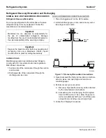
Page 86: ...cuation Connections 3 Open backseat the high and low side ice machine service valves and open high and low side on manifold gauges 4 Perform recovery or evacuation A Recovery Operate the recovery unit as directed by the manufacturer s instructions B Evacuation prior to recharging Pull the system down to 500 microns Then allow the pump to run for an additional half hour Turn off the pump and perfor...

Page 87: ...hat no refrigerant contamination or loss occurs 8 Make sure that all of the vapor in the charging hoses is drawn into the ice machine before disconnecting the charging hoses A Run the ice machine in freeze cycle B Close the high side service valve at the ice machine C Open the low side service valve at the ice machine D Open the high and low side valves on the manifold gauge set Any refrigerant in...

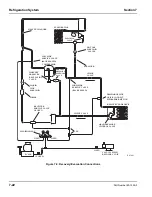
Page 88: ...ENSER CLOSED SCALE OPEN RECOVERY UNIT VACUUM PUMP SERVICE VALVE 1 2 OPEN RECEIVER MANIFOLD SET OPEN DRIER SOLENOID LINE VALVE REGULATING PRESSURE HARVEST LIQUID BACKSEATED SERVICE VALVE CHECK VALVE TEE OPEN C B R HIGH SIDE BACKSEATED SERVICE VALVE LOW SIDE COMPRESSOR HARVEST PRESSURE SOLENOID VALVE VALVE EXPANSION VALVE CHECK STRAINER VALVES SOLENOID HOT GAS HEAT EXCHANGER EVAPORATOR SV1461 ...

Page 89: ...open suction and discharge lines at the compressor for burnout deposits 5 If no signs of contamination are present perform an acid oil test Check the chart below to determine the type of cleanup required Important Manitowoc Ice Inc assumes no responsibility for the use of contaminated refrigerant Damage resulting from the use of contaminated refrigerant is the sole responsibility of the servicing ...

Page 90: ...cuum test to make a preliminary leak check You should use an electronic leak detector after system charging to be sure there is no leak 5 Charge the system with the proper refrigerant to the nameplate charge 6 Operate the ice machine Severe System Contamination Cleanup Procedure 1 Remove the refrigerant charge 2 Remove the compressor 3 Disassemble the harvest solenoid valve If burnout deposits are...

Page 91: ... and change the liquid line drier 14 Follow normal evacuation procedures REPLACING PRESSURE CONTROLS WITHOUT REMOVING REFRIGERANT CHARGE This procedure reduces repair time and cost Use it when any of the following components require replacement and the refrigeration system is operational and leak free Water regulating valve water cooled only High pressure cut out control High side service valve Lo...

Page 92: ...Refrigeration System Section 7 7 26 Part Number 80 1559 3 Figure 7 10 Using Pinch Off Tool SV1406 ...

Page 93: ...refrigerant Listed below are the recommended O E M field replacement driers TOTAL SYSTEM REFRIGERANT CHARGES NOTE All ice machines on this list are charged using R 404A refrigerant Additional Refrigerant Charges For line sets between 50 100 Model Drier Size End Connection Size Part Number Self Contained Water Cooled UK 032S 1 4 89 3025 9 Suction Filter UK 165S 5 8 89 3028 3 Suction Filter used whe...

Page 94: ...op Reclaim To reprocess refrigerant to new product specifications see below by means which may include distillation A chemical analysis of the refrigerant is required after processing to be sure that product specifications are met This term usually implies the use of processes and procedures available only at a reprocessing or manufacturing facility Chemical analysis is the key requirement in this...

Page 95: ...t Re use of recovered or recycled refrigerant from other products is not approved Recycling equipment must be certified to ARI Standard 740 latest edition and be maintained to consistently meet this standard Recovered refrigerant must come from a contaminant free system To decide whether the system is contaminant free consider Type s of previous failure s Whether the system was cleaned evacuated a...

Page 96: ... For systems found without any positive refrigerant pressure assume that moisture has entered the POE oil After the leak is found and repaired the compressor oil must be changed The compressor must be removed and at least 95 of the oil drained from the suction port of the compressor Use a measuring cup to replace the old oil with exactly the same amount of new POE oil such as Mobil EAL22A Remember...

Page 97: ...Section 7 Refrigeration System Part Number 80 1559 3 7 31 THIS PAGE INTENTIONALLY LEFT BLANK ...

Page 98: ...Refrigeration System Section 7 7 32 Part Number 80 1559 3 THIS PAGE INTENTIONALLY LEFT BLANK ...

Page 99: ......

Page 100: ...aining on a Variety of Equipment Breakfast Lunch and Hotel Room Included with Tuition Contact Your Distributor or Manitowoc Ice Inc for Details OR Visit Our Website at www manitowocice com for School Dates MANITOWOC ICE INC 2110 South 26th Street P O Box 1720 Manitowoc WI 54221 1720 Phone 920 682 0161 Service Fax 920 683 7585 Web Site www manitowocice com 2005 Manitowoc Ice Inc ...

Reviews: