background image

6-1

Section 6

Service

Section 6

Electrical System

P MODEL POINT OF USE
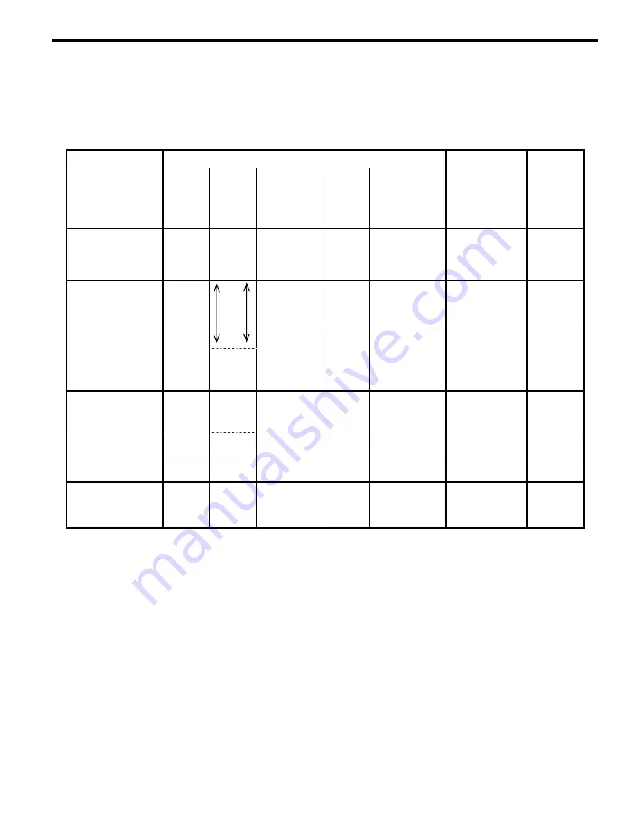
Ice Making Sequence of operation Chart

Control Board Relays

Contactor

SEQUENCE

1

2

3

4

5

3A

of

OPERATION

WATER

PUMP

WATER

FILL

VALVE

CONTACTOR

COIL

WATER

DUMP

VALVE

SUCTION LINE

SOLENOID

EVAPORATOR

HEATERS

LENGTH

of

TIME

INITIAL START-UP/
START UP AFTER
AUTO SHUT-OFF:

1.  Water Purge

on

off

off

on

off

off

45

Seconds

FREEZE
SEQUENCE:

2.  Prechill

off

May

cycle

on/off

for first

off

off

on

off

30

Seconds

45

seconds

3.  Freeze

on

Cycle on

then off

1 more

time

off

off

on

off

Until

10 second

water contact

with ice

thickness

probe

HARVEST
SEQUENCE:

4.  Water Purge

on

30 sec.

off

on

on

off

on

Water purge

factory set at

45

15 sec.

on

Seconds

5.  Harvest

off

off

on

off

off

on

Bin switch

activation

6.

AUTO SHUT-OFF

off

off

off

off

off

off

Until

bin switch

re-closes

Control Board Safety Timers
Freeze Sequence:


The ice machine is locked in the freeze

sequence for the first 6 minutes, not allowing the ice
thickness probe to initiate a harvest sequence.


The maximum freeze time is 60 minutes, at

which time the control board automatically initiates
a harvest sequence (steps 4-5).


The maximum "on time" for the water fill valve

is 6 minutes, at which time it automatically turns
off.

Harvest Sequence:


The maximum "on time" for evaporator heaters
is 5.5 minutes, at which time the contactor will
automatically de-energize to shut the heaters
off.


The maximum harvest time is 6-1/2 minutes, at
which time the control board automatically
terminates the harvest sequence. If the bin
switch is open, the ice machine will go to
Automatic shut-off (step 6). If the bin switch is
closed, the ice machine will go to the freeze
sequence (steps 2-3).

Summary of Contents for P Series

Page 1: ...rvice Manual Thank you for selecting a Manitowoc Ice Machine the dependability leader in ice making equipment and related products With proper care and maintenance your new Manitowoc Ice Machine will provide you with many years of reliable and economical performance ...

Page 2: ...Part Number 80 1125 3 ...

Page 3: ...e sure to read the procedural notices in this manual These notices supply helpful and important information Throughout this manual you will see the following types of procedural notices Important Important boxes serve two functions They call the operator s attention to important information They also provide the service technician with information that may help in performing a procedure more effic...

Page 4: ......

Page 5: ...ime Specifications and design are subject to change without notice MANITOWOC ICE INC 2110 South 26th Street P O Box 1720 Manitowoc WI 54221 1720 Phone 920 682 0161 Service Fax 920 683 7585 Web Site http www manitowocice com ã1998 Manitowoc Ice Inc Litho in USA ...

Page 6: ...harge 2 5 Pre Charged Lineset Installation Routing Pre Charged Linesets 2 7 Lengthening or Reducing Line Set Lengths 2 8 Connecting a Lineset 2 9 Lineset Service Valves 2 9 Installation Checklist 2 10 Before Starting the Ice Machine 2 10 Section 3 Ice Machine Operation Component Identification 3 1 Ice Making Sequence of Operation 3 2 Operational Checks 3 4 Section 4 Maintenance General 4 1 Ice Mac...

Page 7: ...st Safety Limit Light 6 12 Freeze Time Lock In Feature 6 12 Maximum Freeze Time 6 12 Ice Thickness Check 6 12 Diagnosing Ice Thickness Control Circuitry Ice Machine Does Not Cycle Into Harvest 6 13 Ice Machine Prematurely Cycles Into Harvest 6 14 Water Level Control Circuitry Water Level Probe Light 6 15 Freeze Cycle Water Level Setting 6 15 Water Inlet Valve Safety Shut off 6 15 Freeze Cycle Circ...

Page 8: ...SYSTEM Engineered specifically for Manitowoc ice machines Tri Liminator water filters are an efficient dependable and affordable method of inhibiting scale formation filtering sediment and removing chlorine taste and odor MANITOWOC CLEANER AND SANITIZER Manitowoc Ice Machine Cleaner and Sanitizer are available in convenient 16 oz 473 ml bottles These are the only cleaner and sanitizer approved for...

Page 9: ...itowoc distributor service representative or Manitowoc Ice Inc The model and serial number are listed on the OWNER WARRANTY REGISTRATION CARD They are also listed on the MODEL SERIAL NUMBER DECAL affixed to the ice machine Model Serial Number Location Ice Machine Model Number Serial Number Model Number Serial Number Model Number Serial Number Model Number Serial Number SV1700A P 530 MODEL SERIAL N...

Page 10: ...ollowing items are not included in the ice machine s warranty coverage 1 Condensing unit parts compressor ect or repairs Contact the condensing unit manufacturer for warranty information 2 Normal maintenance adjustments and cleaning as outlined in this manual 3 Repairs due to unauthorized modifications to the ice machine or use of non standard parts without prior written approval from Manitowoc Ic...

Page 11: ...1 4 General Information Section 1 THIS PAGE INTENTIONALLY LEFT BLANK ...

Page 12: ...he name of the nearest Manitowoc distributor or call Manitowoc Ice Inc for information regarding start up services Important Failure to follow these installation guidelines may affect warranty coverage Ice Machine Dimensions P 520 ICE MACHINE P 530 ICE MACHINE 8 12 5 00 9 34 2 31 1 25 1 39 7 50 9 65 22 00 14 75 26 50 3 12 30 00 21 75 12 87 2 62 5 31 7 62 9 43 4 00 1 80 SV1719A SV1697A ...

Page 13: ...anty See Removal from Service Winterization on page 4 10 Location of Condensing Unit The location selected for the condensing unit must meet the following criteria If any of these criteria are not met select another location The location must allow connection of all pre charged line sets with out exceeding total distance rise or drop guidelines see page 2 7 Refer to the manual supplied with the co...

Page 14: ...location materials used length of run etc so it must be determined by a qualified electrician P 520 P 530 ICE MACHINES Ice Machine Voltage Phase Cycle Maximum Fuse Circuit Breaker Minimum Circuit Amps P 520 and P 530 115 1 60 20 16 CONDENSING UNIT Refer to nameplate for correct voltage and amperage ratings Scroll compressors will compress in one direction of rotation only Three phase compressor mo...

Page 15: ... other equipment are working Check valves on sink faucets dishwashers etc If water pressure exceeds the maximum recommended pressure obtain a water pressure regulator from your Manitowoc distributor Install a water shut off valve for the ice making water line Insulate water inlet lines to prevent condensation DRAIN CONNECTIONS Follow these guidelines when installing drain lines to prevent drain wa...

Page 16: ...er Pressure Ice Machine Fitting Tubing Size Up to Ice Machine Fitting Ice Making Water Inlet 33 F 0 6 C Min 90 F 32 2 C Max 20 psi 137 9 kPA Min 80 psi 551 5 kPA Max 3 8 Female Pipe Thread 3 8 9 5 mm minimum inside diameter Ice Making Water Drain 1 2 Female Pipe Thread 1 2 12 7 mm minimum inside diameter Bin Drain 3 4 Female Pipe Thread 3 4 19 1 mm minimum inside diameter ...

Page 17: ...prepared to hook up a vacuum pump immediately after brazing Recover the refrigerant charge in the condensing unit Braze tubing for the additional ice machine to the manifold assembly Replace the condensing unit line drier Perform a leak test evacuate system to 250 microns and weigh in the correct refrigerant charge Model Total refrigerant amount R 404A as shipped from factory Additional Refrigeran...

Page 18: ...uidelines drawings and calculation methods must be followed to verify a proper installation Maximum line set distance is 50 per ice machine Maximum line set rise is 35 per ice machine Maximum line set drop is 35 per ice machine Any line set routed below the condensing unit is considered drop Any line set routed above the condensing unit is considered rise Line set rise drop horizontal runs or comb...

Page 19: ... lines suction line shut off valves and components to prevent condensation and sweating 4 Keep outdoor refrigerant line runs as short as possible CAUTION If a line set has a rise followed by a drop another rise cannot be made Likewise if a line set has a drop followed by a rise another drop cannot be made LENGTHENING OR REDUCING LINE SET LENGTHS In most cases by routing the line set properly short...

Page 20: ...ch until they bottom out 5 Turn an additional 1 4 turn to ensure proper brass to brass seating Torque to the following specifications Liquid Line Suction Line 10 12 ft lb 13 5 16 2 N m 35 45 ft lb 47 5 61 0 N m 6 Check all fittings for leaks LINE SET SERVICE VALVE Lines set service valves leave the factory in the open position Verify all line set service valves are open and insulated Important Che...

Page 21: ... Are all electrical leads free from contact with refrigeration lines and moving equipment Has the owner operator been instructed regarding maintenance and the use of Manitowoc Cleaner and Sanitizer Has the owner operator completed the warranty registration card Has the ice machine and bin been sanitized Before Starting the Ice Machine All Manitowoc ice machines are factory operated and adjusted be...

Page 22: ...XPANSION VALVE WATER LEVEL PROBE WATER TROUGH WATER PUMP SUCTION SOLENOID VALVE WATER CURTAIN CONTROL BOX ICE THICKNESS PROBE AEROQUIP FITTINGS ON OFF CLEAN TOGGLE SWITCH LINE DRIER EXPANSION VALVE HARVEST HEATER THERMOSTAT SUCTION SOLENOID VALVE LINE DRIER AEROQUIP FITTINGS POTABLE WATER DRAIN POTABLE WATER INLET ELECTRICAL INLET POTABLE WATER INLET POTABLE WATER DRAIN HARVEST HEATER THERMOSTAT A...

Page 23: ...o run and the water dump valve energizes for 45 seconds to purge the water in the sump trough The water fill valve energizes for the last 15 seconds of the 45 second water purge After the 45 second water purge the water pump water fill valve and water dump valve de energize The evaporator heaters energize at the beginning of the water purge to warm the evaporator The suction line solenoid de energ...

Page 24: ...3 3 Section 3 Ice Machine Operation THIS PAGE INTENTIONALLY LEFT BLANK ...

Page 25: ...ncorrect check the water level probe for damage probe bent etc Repair or replace the probe as necessary Water Level Probe ICE THICKNESS CHECK The ice thickness probe is factory set to maintain the ice bridge thickness at 1 8 3 2 mm NOTE Make sure the water curtain is in place when performing this check It prevents water from splashing out of the water trough 1 Inspect the bridge connecting the cub...

Page 26: ...r purge may be set to 15 30 or 45 seconds During the harvest sequence water purge the water fill valve energizes and de energizes by time The water purge must be at the factory setting of 45 seconds for the water fill valve to energize during the last 15 seconds of the water purge If it is set to less than 45 seconds the water fill valve will not energize during the water purge WARNING Disconnect ...

Page 27: ...3 6 Ice Machine Operation Section 3 THIS PAGE INTENTIONALLY LEFT BLANK ...

Page 28: ...ing the condenser Check all water fittings and lines for leaks Also make sure the refrigeration tubing is not rubbing or vibrating against other tubing panels etc Exterior Cleaning Clean the area around the ice machine as often as necessary to maintain cleanliness and efficient operation Sponge any dust and dirt off the outside of the ice machine with mild soap and water Wipe dry with a clean soft...

Page 29: ...ral deposits It is not used to remove algae or slime Refer to Self Sanitizing Procedure on the next page for removal of algae and slime Step 1 Set the toggle switch to the OFF position after ice falls from the evaporator at the end of a Harvest cycle Or set the switch to the OFF position and allow the ice to melt off the evaporator CAUTION Never use anything to force ice from the evaporator Damage...

Page 30: ...anitizer P 520 P 530 3 ounces 90 ml Step 4 The ice machine will automatically time out a ten minute sanitizing cycle followed by six rinse cycles and then stop This entire cycle lasts approximately 25 minutes Note If the bin requires sanitizing remove all of the ice and sanitize it with a solution of 1 ounce 30 ml of sanitizer with up to 4 gallons 15 L of water Step 5 When the self sanitizing proc...

Page 31: ... Solution Type Water Mixed With Cleaner 1 gal 4 l 16 oz 500 ml cleaner Sanitizer 4 gal 15 l 1 oz 30 ml sanitizer 4 Use a soft bristle brush or sponge NOT a wire brush to carefully clean the parts CAUTION Do not mix Cleaner and Sanitizer solutions together It is a violation of Federal law to use these solutions in a manner inconsistent with their labeling CAUTION Do not immerse the water pump motor...

Page 32: ...top of the coil 3 Note the position of the coil assembly on the valve for assembly later Leaving the wires attached lift the coil assembly off the valve body and the enclosing tube 4 Press down on the plastic nut on the enclosing tube and rotate it 1 4 turn Remove the enclosing tube plunger and plastic gasket from the valve body NOTE At this point the water dump valve can easily be cleaned If comp...

Page 33: ...cket assembly off the screws Ice Thickness Probe 1 Compress the side of the ice thickness probe near the top hinge pin and remove it from the bracket Ice Thickness Probe Removal NOTE At this point the ice thickness probe can easily be cleaned If complete removal is desired continue with step 2 below WARNING Disconnect the electric power to the ice machine at the electric service switch box 2 Disco...

Page 34: ...n the valve 3 When the ice machine is on the water inlet valve must allow the proper water flow through it Set the toggle switch to ON Watch for water flow into the ice machine If the water flow is slow or only trickles into the ice machine remove disassemble and clean the valve Follow the procedure below to remove the water inlet valve WARNING Disconnect the electric power to the ice machine at t...

Page 35: ...he locating pin is clear of the hole before sliding the distribution tube out 4 Disassemble for cleaning A Twist both of the inner tube ends until the tabs line up with the keyways B Pull the inner tube ends outward Water Distribution Tube Disassembly Water Curtain 1 Gently flex the curtain in the center and remove it from the right side Water Curtain Removal 2 Slide the left pin out SV1620 SV1211...

Page 36: ...2 Depress the pressure release button to relieve the pressure 3 Unscrew the housing from the cap 4 Remove the used filter cartridge from the housing and discard it 5 Remove the O ring from the housing groove Wipe the housing groove and the O ring clean 6 Lubricate the O ring with petroleum jelly 7 Press the O ring into the housing groove 8 Insert a new filter cartridge into the housing Make sure i...

Page 37: ...ater from the water trough 4 Disconnect and drain the incoming ice making water line at the rear of the ice machine 5 Move the Ice Off Clean toggle switch to Ice and blow compressed air in the drain opening until no more water comes out of the drain line 6 Wait until the compressor starts then blow compressed air in the incoming water opening in the rear of the ice machine until no more water come...

Page 38: ...release ice or is slow to harvest Ice machine is dirty Clean and sanitize the ice machine See pages 4 2 and 4 3 Ice machine is not level Level the ice machine See page 2 2 Ice machine does not cycle into harvest mode The six minute freeze time lock in has not expired yet Wait for freeze lock in to expire Ice thickness probe is dirty Clean and sanitize the ice machine See pages 4 2 and 4 3 Ice thic...

Page 39: ...an the dump valve See page 4 5 Safety Limit Feature In addition to the standard safety controls your Manitowoc ice machine features built in safety limits which will stop the ice machine if conditions arise which could cause a major component failure Safety Limit Stand By Mode The first time a safety limit shut down occurs the ice machine turns off for 60 minutes Stand by Mode The ice machine will...

Page 40: ... switch activation 6 AUTO SHUT OFF off off off off off off Until bin switch re closes Control Board Safety Timers Freeze Sequence The ice machine is locked in the freeze sequence for the first 6 minutes not allowing the ice thickness probe to initiate a harvest sequence The maximum freeze time is 60 minutes at which time the control board automatically initiates a harvest sequence steps 4 5 The ma...

Page 41: ... machine to the freeze cycle This occurs when the bin switch is opened and closed again within 7 seconds during the harvest cycle 2 Automatic ice machine shut off If the storage bin is full at the end of a harvest cycle the sheet of cubes fails to clear the water curtain and holds it open After the water curtain is held open for 7 seconds the ice machine shuts off The ice machine remains off until...

Page 42: ...losed Resistance readings of less than 70 ohms indicates a correctly operating bin switch Important Any reading between 70 and 30 000 ohms regardless of curtain position indicates a defective bin switch Bin Switch Resistance Readings Water Curtain Removal Notes The water curtain must be on bin switch closed to start ice making While a freeze cycle is in progress the water curtain can be removed an...

Page 43: ... 67 68 Open 67 69 Closed 66 62 Open OFF 67 68 Open 67 69 Open 4 Replace the toggle switch if ohm readings do not match all three switch settings HARVEST HEATER ELEMENT Function Warms the evaporator in the harvest cycle allowing the ice to release Specifications Model Volt Amp Ohm Upper 115 9 4 to 11 5 10 4 to 12 1 Lower 115 5 1 to 6 2 19 3 to 22 5 Listed ohm values are at room temperature Check Pr...

Page 44: ...n the suction pressures reach s the cut in setpoint Specifications Adjustable cut in and cut out Factory Setting Cut in 25 psig Cut out 3 psig These are minimum setpoints The cut in can be increased when low ambient temperatures will not be experienced Check Procedure NOTE The suction pressure must exceed the cut in setpoint to close the switch The switch will then remain closed until the suction ...

Page 45: ...on solenoid valve must be open 3 Move the Ice Off Clean toggle switch to the off position 4 The meter reading must be 0 volts and the suction solenoid valve must be closed LINE SET ISOLATION VALVES FUNCTION Isolates ice machine evaporator from refrigeration system Allows discharge and suction pressure readings to be taken at the schraeder valve fitting SPECIFICATIONS Liquid Line 1 4 inlet 1 4 outl...

Page 46: ... to the bulkhead 14 Lift the evaporator assembly out through the front of the ice machine P 520 1 Disconnect power to the ice machine at the service disconnect or breaker 2 Remove front back side and top panels 3 Disconnect wiring to the harvest heaters and suction solenoid coil 4 Remove bin switch from evaporator extrusion 5 Frontseat close the isolation valves on the liquid and suction line sets...

Page 47: ...ervice section of this manual for information relating to how the probe and control board functions together This section will include items such as How a harvest cycle is initiated How the harvest light functions with the probe Freeze time lock in feature Maximum freeze time Diagnosing ice thickness control circuitry 1G N 115V L2 208 230V L1 PRIMARY POWER SUPPLY SV1588 1F 1C 57 55 58 60 61 56 20 ...

Page 48: ...densers water loss to the ice machine etc The safety limits protect the ice machine primarily the compressor from external failures by stopping ice machine operation before major component damage occurs The safety limit system is similar to a high pressure cut out control It stops the ice machine but does not tell what is wrong A service technician must analyze the system to determine what caused ...

Page 49: ...efective head pressure control Defective compressor TXV starving or flooding check bulb mounting Non condensibles in refrigeration system Plugged or restricted high side refrigerant lines or component Safety Limit 2 Harvest time exceeds 6 5 minutes for 3 consecutive harvest cycles Possible Cause Check Correct Improper installation See section 2 Installation Instructions Water system Water area eva...

Page 50: ...ce machine will then automatically restart to see if the problem re occurs During the Stand By Mode the harvest light will be flashing If the same safety limit is reached a second time the problem has re occurred the ice machine will initiate a safety limit shut down and remain off until it is manually restarted During a safety limit shut down the harvest light will be flashing Re start the ice ma...

Page 51: ...nutes the harvest light will come on to indicate that water is in contact with the probe but the ice machine will stay in the freeze cycle After the six minutes are up a harvest cycle is initiated This is important to remember when performing diagnostic procedures on the ice thickness control circuitry To allow the service technician to initiate a harvest cycle without delay this feature is not us...

Page 52: ...rectly The harvest light does not come on Proceed to Step 3 below Step 3 Disconnect the ice thickness probe from the control board at terminal 1C Clip the jumper wire leads to terminal 1C on the control board and any cabinet ground Monitor the harvest light Step 3 Step 3 Jumper wire connected from control board terminal 1C to ground Monitoring of Harvest Light Correction The harvest light comes on...

Page 53: ...the harvest light Step 2 Step 2 Disconnect probe from control board terminal 1C Monitoring of Harvest Light Correction The harvest light stays off and the ice machine remains in the freeze sequence The ice thickness probe is causing the malfunction Verify that the Ice Thickness probe is adjusted correctly The harvest light comes on and 6 10 seconds later the ice machine cycles from freeze to harve...

Page 54: ...witches or timers to maintain consistent water level control During the freeze cycle the water inlet valve energizes turns on and de energizes turns off in conjunction with the water level probe located in the water trough During the first 45 seconds of the Freeze Cycle The water inlet valve is on when there is no water in contact with the water level probe The water inlet valve turns off after wa...

Page 55: ...ct a jumper from the water level probe to any cabinet ground Important For the test to work properly you must wait until the freeze cycle starts prior to connecting the jumper wire If you restart the test you must disconnect the jumper wire restart the ice machine step 1 and then reinstall the jumper wire after the water pump starts Step 2 Step 2 Jumper wire connected from probe to ground Is water...

Page 56: ...connecting the jumper wire restarting the ice machine step 1 and then reinstalling the jumper wire to terminal 1F after the water pump starts Step 3 Step 3 Jumper wire connected from control board terminal 1F to ground Is water flowing into the water trough The Water Level Light is The Water Inlet Valve Solenoid Coil is Cause no on De Energized The water level probe is causing the problem Clean or...

Page 57: ...e any parts no on or off Energized Or De Energized Proceed to step 3 Step 3 Leave the ice machine run then disconnect the water level probe from control board terminal 1F Important For the test to work properly you must wait until the freeze cycle starts prior to disconnecting the water level probe If you restart the test you must reconnect the water level probe restart the ice machine step 1 and ...

Page 58: ...er before working on electrical circuitry Drawing shown during freeze cycle 4 1 BACK OF MACHINE IS MARKED AT EACH END OF WIRE BULKHEAD MULTIPIN CONNECTOR TB TERMINAL BOARD CONNECTION WIRE NUMBER DESIGNATION 34 LOWER HEATER ELECTRICAL BOX SIDE 32 UPPER HEATER TB30 TB30 See serial plate for voltage WATER LEVEL SWITCH HARVEST SAFTY CODE CURTAIN SWITCH CLEAN MODE 58 56 57 73 TB31 98 WATER PUMP SUCTION...

Page 59: ...TOR SUCTION LINE KING VALVE LIQUID LINE MANIFOLD LIQUID LINE KING VALVE LIQUID LINE FILTER DRIER RECEIVER HEAD PRESSURE CONTROL VALVE CONDENSER LIQUID LINE DRIER EXPANSION VALVE LIQUID LINE DRIER EXPANSION VALVE EVAPORATOR EVAPORATOR LIQUID LINE DRIER LINE SET ISOLATION VALVES EXPANSION VALVE LINE SET ISOLATION VALVES EVAPORATOR SV1726A ...

Page 60: ... slab weight of 4 02lb to 4 12lbs Individual Ice Capacity Lb 24 Hour 90F Ambient 50F Water 414 497 370 301 526 504 449 355 569 527 498 419 611 576 527 475 100 200 300 400 500 600 700 10 0 10 20 30 40 50 60 70 80 90 100 110 120 Condensing Unit Ambient F Lb 24 Hour 10 4 P500 On 3 P500 On 2 P500 On 1 P500 On Total Ice Capacity Lb 24 Hour 90F Ambient 50F Water 1988 1656 1480 1204 1578 1512 1347 1065 1...

Page 61: ...30 40 50 60 70 80 90 100 110 120 Condensing Unit Ambient F Lb 24 Hour 10 4 P500 On 3 P500 On 2 P500 On 1 P500 On Total Ice Capacity Lb 24 Hour 90F Ambient 70F Water 1168 1500 1412 1752 1047 1212 1293 1428 790 928 968 1048 429 480 510 547 200 400 600 800 1000 1200 1400 1600 1800 2000 10 0 10 20 30 40 50 60 70 80 90 100 110 120 Condensing Unit Ambient F Lb 24 Hour 10 4 P500 On 3 P500 On 2 P500 On 1 ...

Page 62: ... 30 40 50 60 70 80 90 100 110 120 Condensing Unit Ambient F Lb 24 Hour 10 4 P500 On 3 P500 On 2 P500 On 1 P500 On Total Ice Capacity Lb 24 Hour 90F Ambient 90F Water 1592 1472 1220 1076 1293 1194 924 1155 964 880 730 918 546 485 466 419 200 400 600 800 1000 1200 1400 1600 1800 2000 10 0 10 20 30 40 50 60 70 80 90 100 110 120 Condensing Unit Ambient F Lb 24 Hour 10 4 P500 On 3 P500 On 2 P500 On 1 P...

Reviews: