


ELECTRIC SYSTEM
NBT30H-2 SERVICE MANUAL
3-18
03-20-2019 Control # 613-06
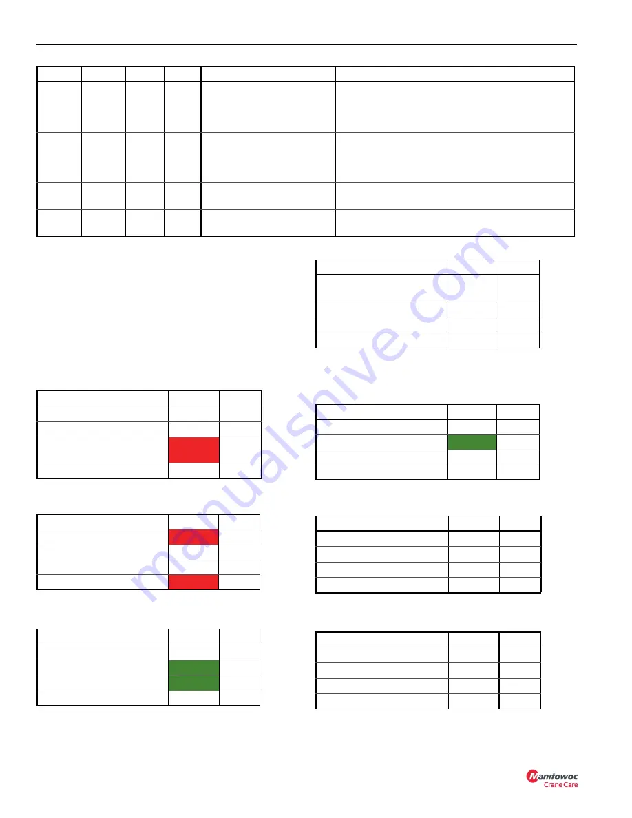
Real Time I/O Screens
The (I/O) input signal and the output signal provides the
operating status and values in real time on the display
console. This allows for certain preliminary diagnosis and
troubleshooting without connecting to external diagnostic
equipment. (Refer to
NOTE:
The following list of I/O Screens Status and Values
are for examples only.
Diagnostic and Real Time I/O Screens
I/O Screen #1:Module Status
I/O Screen #2:RCL CAN Status
I/O Screen #3:E-Stop Status
I/O Screen #4:RCL Sensors
I/O Screen #5:RCL Master Inputs
I/O Screen #6:RCL Master Outputs
I/O Screen #7:RCL Display Inputs
19
12
42
16
RCL Module: Event
Recorder, Data Chart,
Inability to log (FLASH write
failure)
19
12
42
17
RCL Module: Event
Recorder, Data Chart,
Cleared by user (FLASH
cleared)
User has accessed the event recorder login (via RCL
Display) and cleared memory. Both the “Event” and
“Data” chart info is cleared at the same time; related
to error 19.11.1.17.
19
28
43
12
A12, 803, System voltage
low
Voltage at RCL master is less than 10.0 V (18 V if 24
V system)
19
28
43
11
A12, 803, System voltage
high
Voltage at RCL master is greater than 16.0 V (30 V if
24 V system)
Device
Group
Index
Error
Pin, Wire, Description
Possible Causes/Comments
Name
Status
Value
RCL Module:Application
Running
X.XXX
RCL Module:
X.XXX
RCL Display Application
Missing
255.2
55
RCL Display Application
Name
Status
Value
Truck ECM (J1939)
Missing
PC1 CANbus
OK
J1939 CANbus
ERROR
Name
Status
Value
ESTOP State
Clear
Crane
Clear
Name
Status
Value
Pressure Sensor-Base
(psi)
OK
XXXX
Pressure Sensor-Rod (psi)
OK
XXXX
Boom Length Sensor (cnts)
OK
XXXX
Boom Angle Sensor (degs)
OK
XXX
Name
Status
Value
RCL Override
OFF
Crane E-Stop
Clear
ON
DRI Movement (Hz)
3
Remote Enable Switch
OFF
Name
Status
Value
Crane Function Enable
Normal
On
Lockout Lamp
Normal
Off
Swing Left
Normal
0
Swing Right
Normal
0
Name
Status
Value
Throttle Pedal-DS (mV)
Normal
0
Throttle Pedal-PS (mV)
Normal
451
High Hydraulic Oil Temp
Normal
OFF
MWI\DRI Signal
Normal
OFF
Summary of Contents for National Crane NBT30H-2
Page 1: ...Service Manual National Crane NBT30H 2 ...
Page 2: ......
Page 40: ...1 30 03 20 2019 Control 613 06 INTRODUCTION NBT30H 2 SERVICE MANUAL ...
Page 92: ...ELECTRIC SYSTEM NBT30H 2 SERVICE MANUAL 3 24 03 20 2019 Control 613 06 ...
Page 110: ...BOOM MAINTENANCE NBT30H 2 SERVICE MANUAL 4 18 03 20 2019 Control 613 06 ...
Page 132: ...SWING NBT30H 2 SERVICE MANUAL 6 14 03 20 2019 Control 613 06 ...
Page 142: ...OUTRIGGERS NBT30H 2 SERVICE MANUAL 7 10 03 20 2019 Control 613 06 ...
Page 158: ...LUBRICATION NBT30H 2 SERVICE MANUAL 8 16 03 20 2019 Control 613 06 ...
Page 190: ...SCHEMATICS NBT30H 2 SERVICE MANUAL 10 2 ...
Page 193: ......
Page 194: ......


