


HYDRAULIC SYSTEM
NBT30H-2 SERVICE MANUAL
2-20
03-20-2019 Control # 613-06
Oil Cooler Service & Maintenance
The heat exchanger must be kept clean to allow for efficient
operation of the cooler system. Frequent washing of the heat
exchanger core will eliminate oil film, road dirt and other
foreign object buildup on the heat exchanger fins which
reduces cooling efficiency.
Frequent inspection and tightening of hose clamp line
connections will eliminate the possibility of end connection
failure due to back pressure from cold startup.
If cooler system fails to provide adequate performance,
reduced air or oil flow through the heat exchanger is the
probable cause. The cooling fan should be inspected for
proper operation. Any obstructions to air flow should be
corrected (cooler too close to other truck components,
foreign matter in heat exchanger fins, etc.). All hydraulic lines
should be periodically checked for obstructions, hose kinks
or other flow restrictions.
Hydraulic Valves
Directional Control Valve Manifold
The Directional Control Valve Manifold (DCV) controls the
hoist, swing, lift cylinder, telescope cylinder and options,
when installed. Valve spools are mechanically driven by
control levers and the proportional solenoids if equipped with
optional remote controller. The DCV is located at the
operator’s control console behind the console cover.
Inspection
Inspect the DCV for visible damage, binding spools, and
evidence of leakage. If excessive internal leakage is
suspected during operation with a spool in its center position,
it is possible that the area between the spool and working
section bore of the valve body is worn beyond serviceable
limits. If this condition exists, the spool and body must be
replaced as an assembly.
Valve Leakage
Dripping hydraulic oil indicates some type of external
leakage. The machine should be removed from service for
immediate repairs. External leaks sometimes develop at
fittings and seals. Spool seals are susceptible since they are
subject to wear. Seals may be damaged by temperatures
that are too high, or by dirt or paint accumulation on the
spool. Damaged seals must be replaced.
A component functioning at reduced efficiency may indicate
that the valve section in the DCV for that component is
leaking internally. If preliminary a check reveals that
adequate volume is being supplied to the affected valve
bank, relief valves are properly adjusted, and the component
is not at fault, check the valve for scored or worn parts.
Scoring is usually a sign of contamination (external
contamination by dust or internal contamination by debris
from deteriorating components or oxidized hydraulic oil).
Scored or severely worn valve components must be
replaced.
Check valves in the DCV are designed to permit a flow of
hydraulic oil in one direction only. If a piece of dirt or rust has
worked its way into the check valve and lodges between the
poppet and seat, it will keep the valve open and allow a
return flow of hydraulic oil. Clean the valve and check that
the hydraulic system filter is still serviceable.
Binding Spools
Some of the most common causes for stiff spool movement
or jammed spool action are system overheating, excessive
pressure, contaminated or deteriorated hydraulic oil, or
warped mountings. When scorched or deteriorated hydraulic
oil or contamination is the cause, flush the system and
replenish with clean hydraulic oil. If the spool bores are badly
scored or galled, the valve must be removed for servicing.
Warping occurs when mounting plates are not level or they
become distorted from machine damage. The valve can be
shimmed level to correct this problem.
Check the valve for rust. Rust or dirt collecting on the valves
can prevent free movement of the spool, and keep it from the
true center position. Excessive system pressure can create
both internal and external leaks in valves that are otherwise
sound. Only qualified technicians using the correct
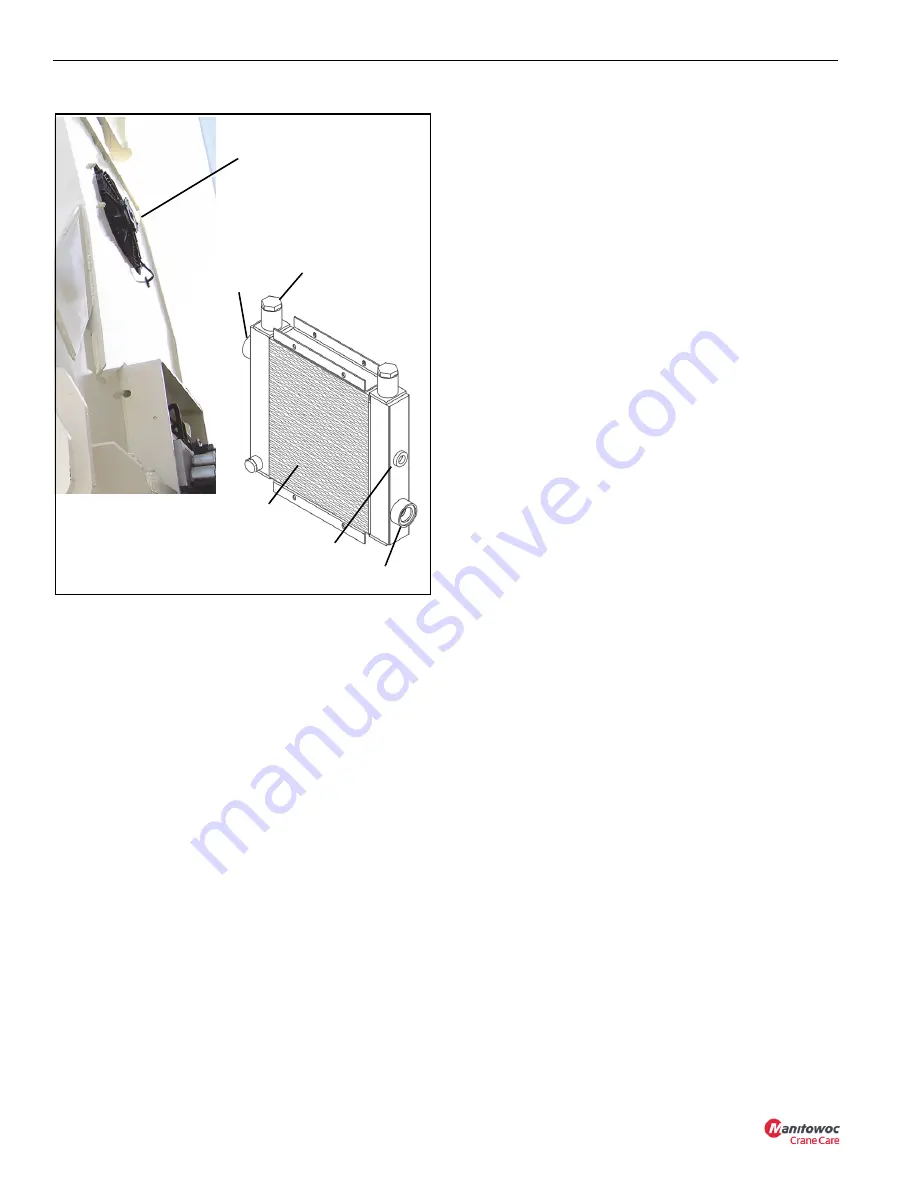
Hydraulic Oil
Cooler
FIGURE 2-13
Outlet
Bypass Valve
Inlet
Temperature
Sensor
Cooling Core
Summary of Contents for National Crane NBT30H-2
Page 1: ...Service Manual National Crane NBT30H 2 ...
Page 2: ......
Page 40: ...1 30 03 20 2019 Control 613 06 INTRODUCTION NBT30H 2 SERVICE MANUAL ...
Page 92: ...ELECTRIC SYSTEM NBT30H 2 SERVICE MANUAL 3 24 03 20 2019 Control 613 06 ...
Page 110: ...BOOM MAINTENANCE NBT30H 2 SERVICE MANUAL 4 18 03 20 2019 Control 613 06 ...
Page 132: ...SWING NBT30H 2 SERVICE MANUAL 6 14 03 20 2019 Control 613 06 ...
Page 142: ...OUTRIGGERS NBT30H 2 SERVICE MANUAL 7 10 03 20 2019 Control 613 06 ...
Page 158: ...LUBRICATION NBT30H 2 SERVICE MANUAL 8 16 03 20 2019 Control 613 06 ...
Page 190: ...SCHEMATICS NBT30H 2 SERVICE MANUAL 10 2 ...
Page 193: ......
Page 194: ......


