


1-18
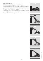
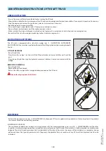
G - TAKING UP AND LAYING A HIGH LOAD ON STABILIZERS
Depending on the model of lift truck
You must not raise the jib if you have not checked the transverse attitude of the lift truck (see: INSTRUCTIONS FOR HANDLING A LOAD: D - TRANSVERSE ATTITUDE
OF THE LIFT TRUCK).
REMINDER: Make sure that the following operations can be performed with good visibility (see: OPERATIONS INSTRUCTIONS UNLADEN AND
LADEN: D - VISIBILITY).
USING THE STABILIZERS
The stabilizers are used to optimise the lift truck’s lifting performances (see: 2 - DESCRIPTION: INSTRUMENTS AND CONTROLS).
POSITION THE STABILIZERS WITH THE FORKS IN TRANSPORT POSITION (UNLADEN AND LADEN)
- Set the forks in transport position in front of the elevation.
- Stay far enough away to have room for the jib to be raised.
- Put the handbrake on and put the gearshift lever into neutral.
- Set the two stabilizers on the ground and lift the two front wheels of the lift truck (fig. G1), while
maintaining its transverse stability.
RAISE THE STABILIZERS WITH THE FORKS IN TRANSPORT POSITION (UNLADEN AND LADEN)
- Raise both stabilizers fully and at the same time.
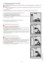
SETTING THE STABILIZERS WITH THE JIB UP (UNLADEN AND LADEN)
This operation must be exceptional and performed with great care.
- Raise the jib and retract the telescopes completely.
- Set the lift truck in position in front of the elevation (fig. G2) moving very slowly and carefully.
- Put the handbrake on and put the gearshift lever into neutral.
- Move the stabilizers very slowly and gradually as soon as they are close to the ground or in
contact with it.
- Lower the two stabilizers and lift the two front wheels of the lift truck (fig. G3). During this
operation, transverse attitude must be permanently maintained: the bubble in the level must
be kept between the two lines.
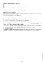
SETTING THE STABILIZERS WITH THE JIB UP (UNLADEN AND LADEN)
This operation must be exceptional and performed with great care.
- Keep the jib up and retract the telescopes completely (fig. G3).
- Move the stabilizers very slowly and gradually as soon as they are in contact with the ground
and when they leave the ground. During this operation, the transverse attitude must be
permanently maintained: the bubble in the level must be kept between the two lines.
- Raise both stabilizers completely.
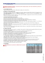
- Release the parking brake and reverse the lift truck (1) very slowly and carefully, to release it
and lower the forks (2) into transport position (fig. G4).
G1
G2
G3
1
2
G4
647421
(22/08/2017)
MT-X
625
Série
2-E3
+
COMFORT
Summary of Contents for MT-X 625 2-E3 Series
Page 5: ...1 1 1 OPERATING AND SAFETY INSTRUCTIONS 647421 22 08 2017 MT X 625 S rie 2 E3 COMFORT...
Page 6: ...1 2 647421 22 08 2017 MT X 625 S rie 2 E3 COMFORT...
Page 32: ...1 28 647421 22 08 2017 MT X 625 S rie 2 E3 COMFORT...
Page 33: ...2 1 2 DESCRIPTION 647421 22 08 2017 MT X 625 S rie 2 E3 COMFORT...
Page 34: ...2 2 647421 22 08 2017 MT X 625 S rie 2 E3 COMFORT...
Page 45: ...2 13 647421 22 08 2017 MT X 625 S rie 2 E3 COMFORT...
Page 69: ...2 37 647421 22 08 2017 MT X 625 S rie 2 E3 COMFORT...
Page 71: ...2 39 647421 22 08 2017 MT X 625 S rie 2 E3 COMFORT...
Page 77: ...3 1 3 MAINTENANCE 647421 22 08 2017 MT X 625 S rie 2 E3 COMFORT...
Page 78: ...3 2 647421 22 08 2017 MT X 625 S rie 2 E3 COMFORT...
Page 83: ...3 7 647421 22 08 2017 MT X 625 S rie 2 E3 COMFORT...
Page 91: ...3 15 647421 22 08 2017 MT X 625 S rie 2 E3 COMFORT...
Page 107: ...3 31 647421 22 08 2017 MT X 625 S rie 2 E3 COMFORT...
Page 112: ...3 36 647421 22 08 2017 MT X 625 S rie 2 E3 COMFORT...
Page 114: ...3 38 647421 22 08 2017 MT X 625 S rie 2 E3 COMFORT...
Page 116: ...4 2 647421 22 08 2017 MT X 625 S rie 2 E3 COMFORT...
Page 118: ...4 4 647421 22 08 2017 MT X 625 S rie 2 E3 COMFORT...
Page 130: ...5 2 647421 22 08 2017 MT X 625 S rie 2 E3 COMFORT...
Page 132: ...5 4 647421 22 08 2017 MT X 625 S rie 2 E3 COMFORT...


