background image

5-1

5 - SPECIFIC AUSTRALIA

See also the operator’s manual supplement: 647065 AU

647421 

(22/08/2017) 

MT-X 

625 

Série 

2-E3 

COMFORT

Summary of Contents for MT-X 625 2-E3 Series

Page 1: ...OPERATOR S MANUAL ORIGINAL INSTRUCTIONS EN 22 08 2017 647421 MT X 625 S rie 2 E3 MT X 625 COMFORT S rie 2 E3...

Page 2: ...given at the time of its design The level of equipment of the lift truck depends on the options chosen and the country of sale According to the lift truck options and the date of sale certain items o...

Page 3: ...e plans designs views commentaries and instructions even the document organization that are found in this document are the intellectual property of MANITOU BF Any violation of the aforementioned may l...

Page 4: ...AND SAFETY INSTRUCTIONS 2 DESCRIPTION 3 MAINTENANCE 4 OPTIONAL ATTACHMENTS FOR USE WITH THE RANGE 5 SPECIFIC AUSTRALIA Seealsotheoperator smanualsupplement 647065AU 647421 22 08 2017 MT X 625 S rie 2...

Page 5: ...1 1 1 OPERATING AND SAFETY INSTRUCTIONS 647421 22 08 2017 MT X 625 S rie 2 E3 COMFORT...

Page 6: ...1 2 647421 22 08 2017 MT X 625 S rie 2 E3 COMFORT...

Page 7: ...BILITY LIMITER AND WARNING DEVICE D TRANSVERSE ATTITUDE OF THE LIFT TRUCK E TAKING UP A LOAD ON THE GROUND F TAKING UP AND LAYING A HIGH LOAD ON TYRES G TAKING UP AND LAYING A HIGH LOAD ON STABILIZERS...

Page 8: ...ng equipment Contact your dealer Take into account climatic and atmospheric conditions of the site of utilisation Protection against frost see 3 MAINTENANCE LUBRICANTS AND FUEL Adaptation of lubricant...

Page 9: ...The operator s manual must always be in good condition and kept in the place provided on the lift truck and in the language used by the operator The operator s manual and any plates or stickers which...

Page 10: ...espect to the use of lift trucks and must be carried permanently by the operator The operator is not competent to authorise the driving of the lift truck by another person C MAINTENANCE The operator m...

Page 11: ...am posted at the operator station reminds you that Left hand column It is forbidden to lift people with any kind of attachment using a non PLATFORM fitted lift truck Right hand column With a PLATFORM...

Page 12: ...or this purpose Do not jump out of the seat to get down Always pay attention when using the lift truck Do not listen to the radio or music using headphones or earphones Never operate the lift truck wh...

Page 13: ...ador theattachmentandthestructureandreadjustthisifnecessary Ifpossibleusethelifttruckatanoiltemperatureascloseaspossibletoambienttemperature In the case of work near aerial lines ensure that the safet...

Page 14: ...IFT TRUCK SAFETY INSTRUCTIONS Operators attentionisdrawntotherisksinvolvedinusingthelifttruck inparticular Riskoflosingcontrol Riskoflosinglateralandfrontalstabilityofthelifttruck Theoperatormustremai...

Page 15: ...LIFT TRUCK SAFETY INSTRUCTIONS Never leave the ignition key in the lift truck during the operator s absence When the lift truck is stationary or if the operator has to leave his cab even for a moment...

Page 16: ...t the steering mode HIGHWAY TRAFFIC as model of lift truck see 2 DESCRIPTION INSTRUMENTS AND CONTROLS Retract entirely the jib and put the attachment at 300 mm from the ground Place the slope correcto...

Page 17: ...RATING THE LIFT TRUCK WITH A TRAILER For using a trailer observe the regulations in force in your country maximum travel speed braking maximum weight of trailer etc Do not forget to connect the traile...

Page 18: ...r a higher centre of gravity contact your dealer For irregular loads determine the transverse centre of gravity before any movement fig B2 and set it in the longitudinal axis of the lift truck Itisfor...

Page 19: ...two lines see 2 DESCRIPTION INSTRUMENTS AND CONTROLS In this position the two front wheels must be off the ground E TAKING UP A LOAD ON THE GROUND Approach the lift truck perpendicular to the load wit...

Page 20: ...ad by alternately extending and retracting the jib 1 or if necessary moving the lift truck forward 2 fig F2 Put the handbrake on and set the forward reverse selector to neutral Slightly lift the load...

Page 21: ...NG DEVICE If necessary move the lift truck 3 forward fig F7 driving very slowly and carefully Place the load in a horizontal position and lay it down on the pile by lowering and retracting the jib 1 2...

Page 22: ...ADEN AND LADEN Thisoperationmustbeexceptionalandperformedwithgreatcare Raise the jib and retract the telescopes completely Set the lift truck in position in front of the elevation fig G2 moving very s...

Page 23: ...et the load down in the place from where it was taken If possible lower the load without moving the lift truck Raise the jib 1 to release the load retract 2 and lower the jib 3 to set the load into tr...

Page 24: ...smoothly to minimise swinging of the load Carry the load a few centimetres above the ground max 30 cm the shortest possible jib length Do not exceed the offset indicated on the load chart If the load...

Page 25: ...aterials to the point where it is necessary to step over them D USING THE PLATFORM However experienced they may be operators must acquaint themselves with the emplacement and operation of all control...

Page 26: ...crests probably spray 7 Near gale 28 33 50 61 13 9 17 1 Whole trees sway it is difficult to walk against the wind Sea heaps up and white foam blown in streaks along the direction of the wind 8 Gale 34...

Page 27: ...inaccessible place The user must ensure that the instruction manual is accessible at all times and that operators have read and understood it INSTRUCTIONS Take up position in a stable place with no r...

Page 28: ...e jib fully Place the safety wedge 1 on the rod of the lifting cylinder and secure with the rod 2 and the pin 3 Slowly lower the jib then stop the hydraulic movements before it comes into contact with...

Page 29: ...t engaged the lift truck may suddenly start to move Do not drop metallic items on the battery Disconnect the battery before working on the electrical circuit WELDING Disconnect the battery before any...

Page 30: ...Run the I C engine for a short time so that the oil and cooling liquid circulate inside Disconnect the battery and store it in a safe place away from the cold after charging it to a maximum Remove th...

Page 31: ...OURS SERVICE Refit and set the tension in the drive belts see 3 MAINTENANCE C EVERY 250 HOURS SERVICE Turn the I C engine using the starter to allow the oil pressure to rise Reconnect the engine cut o...

Page 32: ...1 28 647421 22 08 2017 MT X 625 S rie 2 E3 COMFORT...

Page 33: ...2 1 2 DESCRIPTION 647421 22 08 2017 MT X 625 S rie 2 E3 COMFORT...

Page 34: ...2 2 647421 22 08 2017 MT X 625 S rie 2 E3 COMFORT...

Page 35: ...IDENTIFICATION OFTHE LIFTTRUCK 2 8 CHARACTERISTICS 2 10 FRONT AND REARTIRES 2 12 DIMENSIONS AND LOAD CHART 2 14 INSTRUMENTS AND CONTROLS 2 16 TOWING PIN AND HOOK 2 38 DESCRIPTION AND USE OFTHE OPTION...

Page 36: ...E Soltanto N 268491 N 24653 N 234805 STOP N 296998 3 N 289101 1 2 N 234798 N 288430 4 4 4 5 6 7 8 9 REF PART NUMBER DESCRIPTION 1 234805 Hydraulic coupling instruction 2 296998 Maniscopic safety instr...

Page 37: ...5 4 3 1 CAB OPT K20 F56 F57 F58 F59 F60 F55 F54 F53 F52 F51 F44 F46 F45 F43 F42 F41 40A 20A 50A 80A 60A 20A N 286287 2 REF PART NUMBER DESCRIPTION 1 233088 Preheating element option 2 286287 Fuses 3 2...

Page 38: ...625 COMFORT 7 294831 Screen display function sheet 8 290439 Jib head electrovalve function sheet option 9 288638 Lifting ring on carriage sheet option 10 290183 Bucket instruction on telescope 11 297...

Page 39: ...5 16 17 18 36km h Maxi 10m s N 319018 45 Maxi MT MT X 625 TS AS 2 5T 2500kg MAXI 0 3m Maxi 1 00m Maxi 3m Mini 1 44km h 0 4m s Maxi 9 N 265284 Kg Kg Kg Kg Kg Kg Kg Kg Kg Kg Kg Kg Kg 14 N 290973 F1 F2 F...

Page 40: ...TOR FIG D MANITOU reference Type of codification Serial Nr Manufacturer s Nr Year of manufacture B D C MANITOU BF 44158 ANCENIS CEDEX FRANCE N 295506 MODELE MODEL MODELLO MODELO SERIE SERIES Ann e de...

Page 41: ...OFTHEATTACHMENT FIG I Model Serial Nr Year of manufacture CHASSIS FIG J Lift truck serial Nr N 207701 MODELE N dans la s rie Ann e fabrication Masse vide C d G Tablier Cap Nominale Pression de service...

Page 42: ...pressure in the driver s cab LpA according to standard NF EN 12053 dB 75 cab closed Level of sound power ensured in the LwA environment according to directive 2000 14 EC modified by directive 2005 88...

Page 43: ...laden digging s s 3 5 36 7 Forward tilting unladen s s 3 6 35 6 SPECIFICATIONS AND WEIGHTS Speed of movement for lift truck in standard configuration on flat ground except particular conditions Front...

Page 44: ...HECONTACTSURFACE cm2 HARD SOIL LOOSE SOIL HARD SOIL LOOSE SOIL SOLIDEAL 12 16 5 12PR SKS CLTUBELESS 5 6 350 6 48 3 50 54 100 1100 7 97 4 00 138 275 1250 8 01 4 01 156 312 3250 10 00 5 00 325 650 12 16...

Page 45: ...2 13 647421 22 08 2017 MT X 625 S rie 2 E3 COMFORT...

Page 46: ...1 D2 mm 3275 E mm 5094 F mm 1492 F1 mm 1492 G mm 240 G1 mm 330 G2 mm 253 I mm 603 J mm 797 K mm 1015 L mm 45 N mm 1314 O mm 125 P2 37 P3 52 R mm 3150 S mm 6651 T mm 3935 U1 mm 1920 U2 mm 2054 V mm 470...

Page 47: ...RALIA 0 1 1 2 3 4 5 6 7 5 82 SUIVANT NORME EN 1459 annexe B N 315391 4 3 2 1 0m 3 36 2 85 2 55 2 10 1 60 1 30 1 09 0 5m 68 20 10 2 30 40 50 60 0 800KG 1000KG 1200KG 1500KG 2000KG 2500KG MT MT X 625 64...

Page 48: ...2 16 INSTRUMENTS AND CONTROLS 1 2 10 38 5 1 3 7 8 13 6 16 18 17 22 4 9 14 19 23 25 26 29 15 8 21 20 22 23 27 28 12 30 31 11 35 36 34 24 37 37 39 647421 22 08 2017 MT X 625 S rie 2 E3 COMFORT...

Page 49: ...EERING SELECTION 21 HEATER CONTROL 21 AIR CONDITIONING CONTROLS OPTION AIR CONDITIONING MT X 625 COMFORT 22 HEATING VENTS 23 WINDSCREEN DEMISTER VENTS 24 LEVEL INDICATOR 25 DOOR LOCK 26 DOOR WINDOW OP...

Page 50: ...d the seat will not shift into another position Onlyoperatetheleverbyitsrecessedsection anddonotgraspfrombelow attheriskofcrushingthehand LUMBAR ADJUSTMENT FIG C This increases the comfort of the seat...

Page 51: ...enlystoppingwhenyoupressthisbutton Warning whendriving thelifttruckwillbebroughttoasuddenstop Ifpossible stopthelifttruckbeforeusing theemergencystop 5 BATTERYCUT OFF For quickly disconnecting the bat...

Page 52: ...s running stop the I C engine immediately and check the braking oil level In the event of an abnormal drop in the level consult your dealer RED GENERAL FAULT WARNING INDICATOR LIGHT If the lamp and th...

Page 53: ...number of hours the lift truck has been used As soon as the engine is running the flashing pictogram records the hours of operation MAINTENANCE INTERVAL NOTE When the new lift truck is started the ma...

Page 54: ...fault 520405 Man Machine Interface fault 520406 Man Machine Interface fault 520407 Man Machine Interface fault 520408 Man Machine Interface fault 520409 Man Machine Interface fault 520410 Man Machine...

Page 55: ...tion against forward tip over when making aggravating movements is ensured except when the telescopic boom is retracted DEVICESTATUS HALTED TELESCOPE S INRETRACTEDPOSITION A4 A5 Veryslowintermittentso...

Page 56: ...amp Press this button again to return to HANDLING MODE Protection against forward tip over when making aggravating movements is ensured except when the telescopic boom is retracted NOTE BUCKET MODE re...

Page 57: ...MODE Protection against forward tip over when making aggravating movements is ensured except when the telescopic boom is retracted CONFIGURATION1 DEVICESTATUS HALTED TELESCOPE S INRETRACTEDPOSITION A4...

Page 58: ...off of AGGRAVATING hydraulic movements Hold down button C indicator lamps A9 and C1 lamp will light 60 second time delay and at the same time perform the necessary AGGRAVATING hydraulic movement with...

Page 59: ...ING BRAKE To connect the parking brake press the bottom of the switch The indicator lamp shows when it is in use To disconnect the parking brake press the top of the switch J DISABLING THE AGGRAVATING...

Page 60: ...unit 15A F12 Rear fog lights 5A F13 Not used F14 OPTION Revolving light 7 5A F15 Not used F16 Not used F17 Rear windscreen wiper 10A F18 Front windscreen wiper and windscreen washer 15A F19 Power supp...

Page 61: ...Alwaysreplaceafaultyfusewithanotherofequivalentrating Neveruseafusethathasbeenrepaired F41 Not used F42 Ignition switch 60A F43 Alternator 80A F44 Power supply for fuses in the cab 50A F45 Not used F4...

Page 62: ...aulic movement cut off deactivation 5A F9 Stop light relay supply 15A Reversing light relay supply 15A Reverse buzzer alarm relay supply 15A F10 Wheel alignment 5A F11 Flashing unit 15A F12 Rear fog l...

Page 63: ...thanotherofequivalentrating Neveruseafusethathasbeenrepaired F41 Not used F42 Ignition switch 60A F43 Alternator 80A F44 Power supply for fuses in the cab 50A F45 Not used F46 Preheating I C engine 40...

Page 64: ...essure by interfering with the pressure regulating valve In the eventofsuspectedmalfunction contactyourdealer ANYALTERATIONMAYRENDERTHEWARRANTYNULAND VOID Usethehydrauliccontrolscarefullywithoutjerkin...

Page 65: ...engaged the screen will appear and beep will sound for two seconds During this time the operator can sit back down in the seat and continue advancing or reversing When this time is exceeded the forwar...

Page 66: ...e If your air conditioning does not seem to be working correctly have it examined by your dealer see 3 MAINTENANCE F EVERY2000HOURSOFSERVICE Nevertrytorepairanyfaultsyourself A FAN CONTROL This 3 spee...

Page 67: ...ANDLE 27 DOORWINDOWRELEASEBUTTON 28 HANDLEFORREARWINDOWOPENING EMERGENCY EXIT Use the rear window as an emergency exit if it is impossible to leave the cab by the door 29 STEERINGWHEELADJUSTMENTLEVER...

Page 68: ...eft rear stoplight C Left tail light D Rear fog light E Reversing light F Right tail light G Right rear stoplight H Right rear indicator 34 REVOLVINGLIGHT OPTION The magnetic revolving light must be c...

Page 69: ...2 37 647421 22 08 2017 MT X 625 S rie 2 E3 COMFORT...
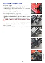
Page 70: ...AL rear view mirror which allows the lift truck to be approached more closely to the trailer ring A TOWINGPIN COUPLING AND UNCOUPLING THE TRAILER To couple the trailer position the lift truck as close...

Page 71: ...2 39 647421 22 08 2017 MT X 625 S rie 2 E3 COMFORT...
Page 72: ...rcuits fuses or circuit breaker and a differential circuit breaker with 30 mA sensitivity Only connect to and disconnect from the power supply while the unit is off and the I C engine is stopped 2 NUM...

Page 73: ...topping it after this time the anti start system reacts and red LED C flashes 6 ANGULARSECTORONJIB The angular sector displays the jib angle and thus improves the reading of the load charts 7 ELECTRIC...

Page 74: ...NTROL Set the valve to position B Push button 3 forward or backward 10 JIBHEADSOLENOIDVALVE MT X 625 COMFORT Enables use of two hydraulic functions on the attachment circuit To make connection of the...

Page 75: ...ease it 12 ATTACHMENTHYDRAULICCONTROLFORCEDOPERATION MT X 625 COMFORT This OPTION must only be used with an attachment requiring continuous hydraulic movement of type brush supply bucket mixer spray I...

Page 76: ...KS AND ATTACHMENTS but the angle of inclination of the carriage must be same as when the forks are used in the horizontal position Check the maximum permitted angle which is 45 Do not change the angle...

Page 77: ...3 1 3 MAINTENANCE 647421 22 08 2017 MT X 625 S rie 2 E3 COMFORT...

Page 78: ...3 2 647421 22 08 2017 MT X 625 S rie 2 E3 COMFORT...

Page 79: ...UBRICANTS AND FUEL 3 8 SERVICING SCHEDULE 3 10 A DAILY OR EVERY 10 HOURS SERVICE 3 12 B EVERY 50 HOURS SERVICE 3 16 C EVERY 250 HOURS OF SERVICE 3 20 D EVERY 500 HOURS SERVICE 3 22 E EVERY 1000 HOURS...

Page 80: ...MAINTENANCEOPERATIONS YOUBENEFIT Through its network MANITOU provides the user with EXPERTISE Know how and competence The guarantee of high quality work Original replacement components Help with preve...

Page 81: ...STEM 01 Service brake and parking brake operation 02 Brake fluid level 105 LUBRICATION AND GREASING 106 JIB MANISCOPIC MANIACCESS ASSEMBLY 01 Beam and telescope s 02 Skid 03 Hinges 04 Carriage 05 Fork...

Page 82: ...er 749473 Change 500 H DRY AIR FILTER CARTRIDGE Part number 563416 Clean 50 H Change 1000 H CYCLONIC PRE FILTER OPTION Part number 224713 Clean 10 H SAFETY DRY AIR FILTER CARTRIDGE Part number 563415...

Page 83: ...3 7 647421 22 08 2017 MT X 625 S rie 2 E3 COMFORT...
Page 84: ...5 COOLING CIRCUIT 12 Liters Cooling liquid protection 25 2 l 5 l 20 l 210 l 788245 788246 788247 788248 Cooling liquid protection 35 20 l 210 l 1000 l 788249 788250 788251 FUEL TANK 63 Liters Diesel f...

Page 85: ...multi purpose 400 g 1 kg 5 kg 20 kg 50 kg 161589 720683 554974 499233 489670 FRONT AXLE ORGANS TO BE LUBRICATED CAPACITY RECOMMENDATION PACKAGING PART NUMBER FRONT AXLE DIFFERENTIAL 4 Liters MANITOU O...

Page 86: ...l water trap 3 20 V V I C engine oil 2 3 22 V V I C engine oil filter 2 3 22 R R Fuel filter 3 23 R R Fuel pre filter 3 25 R R Alternator fan crankshaft belt 3 23 R R Fuel tank 3 26 N I C engine silen...

Page 87: ...3 17 G G G C Transfer box oil level 3 21 C C Front axle differential oil level 3 21 C C Front wheels reducers oil level 3 21 C C Transfer box oil 3 25 V V Front axle differential oil 3 25 V V Front w...

Page 88: ...there is no leakage in the radiator and pipes Toavoidanyriskofsprayingorburning waituntiltheI C enginehascooleddownbeforeremovingthecooling circuit filler plug If the cooling liquid is very hot add o...

Page 89: ...N m 15 Check and adjust the tyre pressures if necessary see 2 DESCRIPTION FRONT AND REAR TYRES Checkthattheairhoseiscorrectlyconnectedtothetyrevalvebeforeinflatingandkeepallpersonsatadistanceduringinf...

Page 90: ...Short press the test button TEST OK One audible beep and progresses to stage 3 TEST NOT OK Two audible beeps and lighting of the fault warning light Exit test mode Go to stage 4 STAGE 3 3 2 1 First an...

Page 91: ...3 15 647421 22 08 2017 MT X 625 S rie 2 E3 COMFORT...

Page 92: ...lean the cartridge seal surfaces with a damp clean lint free cloth and grease with a silicone lubricant MANITOU reference 479292 Check visually the outer condition of the air filter and its mounts Ver...

Page 93: ...ator of the carriage axle 1 lubricator 3 Lubricator of the tilt cylinder head axle 1 lubricator 4 Lubricator of the tilt cylinder foot axle 1 lubricator 5 Lubricator of the lifting cylinder foot axle...

Page 94: ...in the oil level at maximum as cooling depends on the oil flowing through the tank B6 BRAKEOILLEVEL CHECK Place the lift truck on level ground Remove protective casing 1 fig B6 1 using key 2 fig B6 1...

Page 95: ...in ventilation filter 1 fig B8 Clean the filter with a compressed air jet Check its condition and change if necessary see 3 MAINTENANCE FILTERS CARTRIDGES AND BELTS Put the filter back into place B8 1...

Page 96: ...cracks and change if necessary see 3 MAINTENANCE FILTERS CARTRIDGES AND BELTS Check the belt tension between the pulley of the crankshaft and of the compressor Under a normal pressure exerted with th...

Page 97: ...the level plug 1 fig C6 tightening torque 34 to 49 N m C7 REARAXLEDIFFERENTIALOILLEVEL CHECK Place the lift truck on level ground with the I C engine stopped Remove level plug 1 fig C7 The oil should...

Page 98: ...its seal Clean the filter bracket with a clean lint free cloth Lightly grease the new seal before refitting the new oil filter see 3 MAINTENANCE FILTERS AND BELTS on its bracket Tightentheoilfilterbyh...

Page 99: ...ghten screws 3 fig D4 2 by two to three thread turns Swivel the alternator assembly so as to free belt 4 fig D4 2 Pass belt 4 fig D4 3 behind radiator propeller 5 fig D4 3 to remove it and replace wit...

Page 100: ...y 3 and 4 fig D5 3 Separate the head 3 from the filter cartridge 4 fig D5 4 with a twisting motion Refit the head onto a new cartridge see 3 MAINTENANCE FILTERS CARTRIDGES AND BELTS Refit the assembly...

Page 101: ...ig D7 2 tightening torque 34 to 49 N m D8 FRONTAXLEDIFFERENTIALOIL DRAIN Place the lift truck on level ground with the I C engine stopped and the d oil still warm Disposeofthedrainoilinanecologicalman...

Page 102: ...aden atmosphere there are pre filtration cartridges see 3 MAINTENANCE FILTERS CARTRIDGES AND BELTS Also the checking and cleaning periodicity of the cartridge must be reduced up to 250 hours in a heav...

Page 103: ...ng plug 2 fig E4 to ensure that the oil is drained properly Refit and tighten drain plug 1 fig E4 tightening torque 34 to 49 N m Fill up with oil see 3 MAINTENANCE LUBRICANTS AND FUEL through filler p...

Page 104: ...ning of winter Place the lift truck on level ground with the I C engine stopped and cold DRAINING THE LIQUID Place a container under drain plug 1 fig F2 1 and unscrew the plug Open the I C engine bonn...

Page 105: ...KE ACCUMULATOR UNIT FILTER Unscrew plug 3 fig F3 3 lift out the filter and fit a new one see 3 MAINTENANCE FILTERS CARTRIDGES AND BELTS Refit and tighten plug 3 fig F3 3 tightening torque 70 to 80 N m...

Page 106: ...S Do not open the circuit under any circumstances as this would cause the coolant to be lost The cooling circuit contains a gas which can be dangerous under certain conditions This gas coolant R 134a...

Page 107: ...3 31 647421 22 08 2017 MT X 625 S rie 2 E3 COMFORT...
Page 108: ...GE Intheeventofawheelbeingchangedonthepublichighway ensurethefollowing For this operation we advise you to use the hydraulic jack MANITOU reference 505507 and the safety support MANITOU reference 5547...

Page 109: ...WNOFBATTERY CHANGE Open the I C engine bonnet Bring a floating battery of the same type as the one used for the lift truck and battery cables Connect the floating battery according to the correct pola...

Page 110: ...n three turns RELEASING THE PARKING BRAKE ON THE FRONT AXLE Unscrew the screws 2 fig G5 2 on the front axle remove the shims 3 fig G5 2 and fully retighten the screws 2 fig G5 2 TOWING Switch on the w...

Page 111: ...urboshaftwithoutlubricationwhentransportingthevehicle LOADING THE LIFT TRUCK Block the wheels of the platform Attach the loading ramps to the platform in such a way as to give the shallowest possible...

Page 112: ...3 36 647421 22 08 2017 MT X 625 S rie 2 E3 COMFORT...
Page 113: ...ut attachments Carriage tilted fully backward Jib fully retracted and in the down position a few centimetres off the ground Short press the test button STAGE 3 2 1 First green led continuously lit Sec...

Page 114: ...3 38 647421 22 08 2017 MT X 625 S rie 2 E3 COMFORT...

Page 115: ...4 1 4 OPTIONAL ATTACHMENTS FOR USE WITH THE RANGE 647421 22 08 2017 MT X 625 S rie 2 E3 COMFORT...

Page 116: ...4 2 647421 22 08 2017 MT X 625 S rie 2 E3 COMFORT...

Page 117: ...4 3 TABLE OF CONTENTS INTRODUCTION 4 5 PICKING UPTHE ATTACHMENTS 4 6 TECHNICAL SPECIFICATIONS OF ATTACHMENTS 4 8 ATTACHMENT SHIELDS 4 14 647421 22 08 2017 MT X 625 S rie 2 E3 COMFORT...

Page 118: ...4 4 647421 22 08 2017 MT X 625 S rie 2 E3 COMFORT...

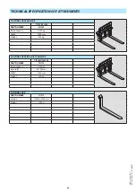
Page 119: ...UCTIONS LOADHANDLINGINSTRUCTIONS H TAKING UPANDSETTING DOWNASUSPENDEDLOAD Only attachments approved by MANITOU are to be used on our lift trucks see 4 ADAPTABLE ATTACHMENTS IN OPTION ON THE RANGE TECH...

Page 120: ...under the locking tube of the attachment slightly lift the jib incline the carriage backwards in order to position the attachment fig C Lift the attachment off the ground to facilitate locking HAND LO...

Page 121: ...he locking pin and the clip on the bracket fig A and lock the attachment fig D Do not forget to refit the clip Stop the I C engine and keep the ignition on the lift truck Release the pressure from the...

Page 122: ...ed capacity 2900 kg Width 1040 mm Weight 285 kg FLOATING FORK SIDE SHIFT CARRIAGE TFF 29 MT 1040 DL PART NUMBER 751378 Rated capacity 2900 kg Side shift 2x100 mm Width 1040 mm Weight 335 kg FLOATING F...

Page 123: ...L 2T5 L1020 FEM2 TDL 2T5 L1260 FEM2 PART NUMBER 751370 751371 Rated capacity 2300 kg 2300 kg Side shift 2x100 mm 2x100 mm Width 1020 mm 1260 mm Weight 54 kg 67 kg LOAD BACK REST PART NUMBER 556320 570...

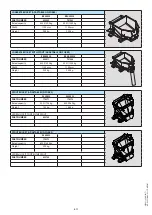
Page 124: ...768 l Width 1850 mm Weight 320 kg LOADING BUCKET CBR 730 L1850 PART NUMBER 571831 Rated capacity 735 l Width 1850 mm Weight 330 kg BUCKET 4X1 CB4x1 700 L1950 PART NUMBER 751402 Rated capacity 700 l Wi...

Page 125: ...capacity 500 l 1300 kg 500 l 1300 kg Width 1100 mm 1100 mm Weight 220 kg 235 kg SPOUT BUCKET ADAPTABLE ON FORKS GL 300 S2 GL 400 S2 PART NUMBER 174371 174372 Rated capacity 300 l 725 kg 400 l 969 kg...

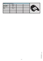
Page 126: ...NURE FORK WITH GRAB FFGR 1700 FFGR 1950 DA PART NUMBER 653012 653048 Rated capacity 2 5 m3 2 9 m3 Width 1700 mm 1950 mm Finger 8 9 Grab 7 7 Weight 505 kg 530 kg 647421 22 08 2017 MT X 625 S rie 2 E3 C...

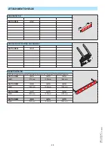
Page 127: ...4 13 SWEEPER COLLECTOR WITH BRUSH BRB 1600 PART NUMBER 790313 Rated capacity 380 l Width 2000 mm Weight 775 kg 647421 22 08 2017 MT X 625 S rie 2 E3 COMFORT...

Page 128: ...h of the bucket PART NUMBER 206734 206732 206730 Width 1375 mm 1500 mm 1650 mm PART NUMBER 235854 206728 206726 Width 1850 mm 1950 mm 2000 mm PART NUMBER 223771 223773 206724 Width 2050 mm 2100 mm 215...

Page 129: ...5 1 5 SPECIFIC AUSTRALIA Seealsotheoperator smanualsupplement 647065AU 647421 22 08 2017 MT X 625 S rie 2 E3 COMFORT...

Page 130: ...5 2 647421 22 08 2017 MT X 625 S rie 2 E3 COMFORT...

Page 131: ...69 50 40 30 20 10 1 5 0 800KG 2000KG 2500KG 1000KG 1200KG 1500KG 0 6m A B C D A B C D MT MT X 625 AUS N 287872 Standard used AS 1418 19 36km h Maxi 10m s Ground conditions solid surface 0 3m Maxi 2500...

Page 132: ...5 4 647421 22 08 2017 MT X 625 S rie 2 E3 COMFORT...

Reviews: